170 Safety functions
SSE with emergency ramp
This applies when the SSE function has been configured as “Emergency ramp” (with
ramp monitoring or time monitoring).
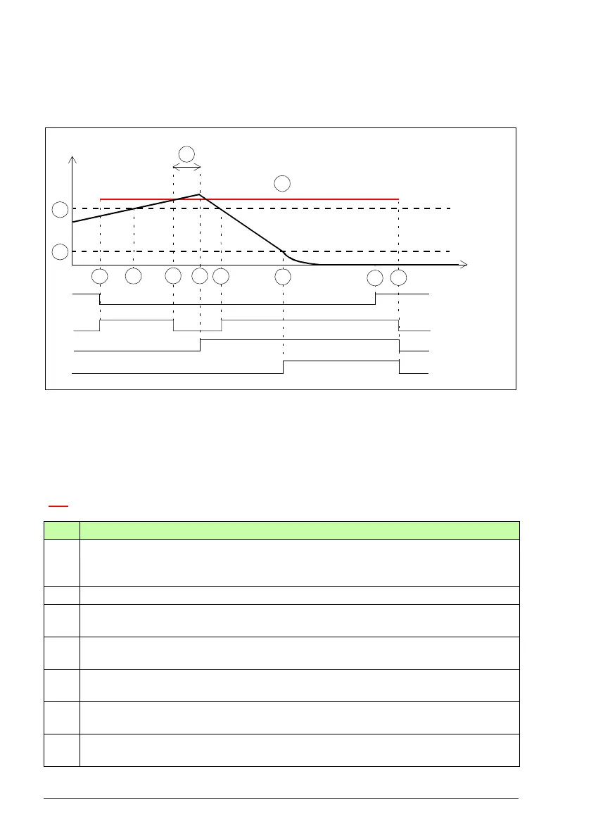
A SLS trip limit positive (parameter SLSx.14, SLSx.23, SLSx.33 or SLSx.43)
B SLS limit positive (parameter 200.23, 200.33, 200.43 or 200.53)
C Response time (depends on system configuration, see page 532)
D Zero speed limit (parameter FSOGEN.51 or FSOGEN.52): Speed limit to define the
motor as stopped. The safety function is completed and the SSE completed indication
(parameter SSE.22) goes on. The acknowledgment becomes allowed.
SLS trip limit (A)
Step Description
1 The SLS request is received, the motor speed is below the SLS limit positive (B) and
the FSO starts the SLS monitoring. The SLS indication (parameter SLSx.15, SLSx.24,
SLSx.34 or SLSx.44) goes on.
2 The motor speed goes above the SLS limit positive (B).
3 The motor speed reaches the SLS trip limit positive (A). The SLS active indication goes
off.
4 After time C has elapsed, the FSO activates the SSE function and the drive starts the
ramp down the motor speed. SAR0 parameter 200.102 defines the ramp.
5 The motor speed goes below the SLS limit positive (B) and the SLS active indication
goes on.
6 The motor speed reaches the zero speed limit (D). The motor has stopped and the
FSO opens the drive STO circuit. The SSE completed indication goes on.
7 The SLS request is removed. The SLS monitoring is still on (acknowledgement method
is manual or from a safety PLC).
SLS indication
SLS request
Motor speed
Time
A
8
1
7
B
4
3
C
SSE state &
indication
SSE completed
indication
2
D
6
5
- -> Safe stop emergency (SSE)