Servo System System Description
16 Product Manual
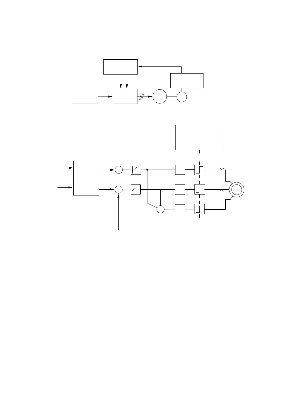
The following diagrams outline the system structure for AC operation as well as the
fundamental structure of the drive unit.
Figure 13 System structure for AC operation.
3.4 Overload protection
PTC resistance is built into the robot motors to provide thermal protection against over-
loads. The PTC sensors are connected to an input on the panel unit which is sensitive
to resistance level and which check that low resistance is maintained.
The robot computer checks the motors for overloading at regular intervals by reading
the panel unit register. In the event of an overload, all motors are switched off.
-
-
+
+
+
-
-
V
W
Computer
DC link
Drive Unit
M
R
Serial measurement
board
Torque reference
AC OPERATION
U
PWM
PWM
PWM
M
M M
+
CURRENT
REGULATOR
M
+
-
MAIN
CIRCUITS
DC link
Rotor position
CURRENT
ESTIMATOR
TORQUE
reference
ROTOR
POSITION
 Loading...


