Disassembly/Assembly
Guidelines
IRB 6400
Page 5 - 15
Axis 1 Guidelines
5. MOUNT GEAR REDUCTION UNIT (S59) TO BASE HOUSING (B24):
a. Remove guide rods.
b. Insert screws (S50) and (S53) apply Loctite 577 (S51).
c. Remove screws (S50), apply Loctite 577 (S51), and re-insert with
washers (S52). Just touch-tighten screws.
d. Rotate input shaft of gear reduction unit ten times back and forth
using tool (#3HAB 1067-6).
e. Tighten screws (S50). Torgue to 224 ft-lb.
f. Tighten screws (S53). Torque to 90 ft-lb.
6. RE-MOUNT SYNC PLATE BRACKET AT LEFT SIDE, TOP OF BASE
HOUSING (B24).
7. REMOVE LIFTING EQUIPMENT.
8. CONNECT LOWER CABLE (B18) CONNECTORS:
a. Connect the following connectors: R2.CS, R2.CP, R2.MP5-6,
R2.MP4, R2.MP3, R2.MP2, and R2.FAN (if fan installed).
b. Connect the following connectors to brake release unit (S64):
R3.BU4-6(X10), R3.BU1-6(X8), R3.BU1-3(X9).
c. Mount brake release unit (S64) with screws (S65).
9. CONNECT LOWER CABLE (B18) TO SUPPORT RAIL:
a. Apply Loctite 242 (B21) to screws (B20).
b. Insert screws (B20) with washers (B19) and tighten.
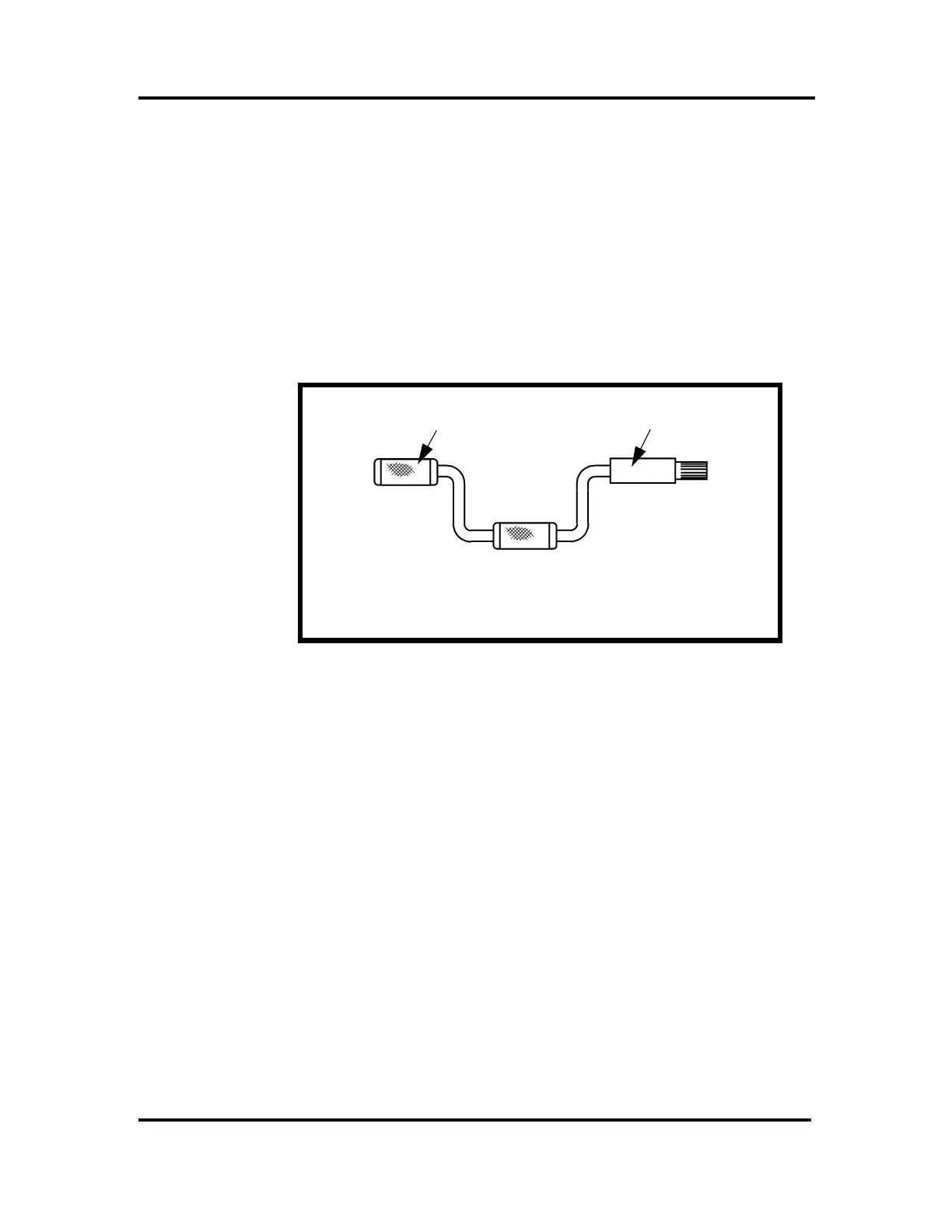
TOOL ABB #3HAB 1067-6
PINION (S18)
PUT PINION ON TOOL
TO ROTATE GEAR
REDUCTION UNIT

 Loading...


