U_A
U_C
U_B
ST_B
ST_C
ST_A
DIPST
INTST
SWELLST
SWELLOPR
INTOPR
DIPOPR
Voltage
Int set
Voltage dip set
Voltage swell set
FALSE
TRUE
FALSE
TRUE
FALSE
TRUE
FALSE
TRUE
FALSE
TRUE
FALSE
TRUE
FALSE
TRUE
FALSE
TRUE
FALSE
TRUE
ST_B
ST_C
ST_A
DIPST
INTST
SWELLST
SWELLOPR
INTOPR
DIPOPR
FALSE
TRUE
FALSE
TRUE
FALSE
TRUE
FALSE
TRUE
FALSE
TRUE
FALSE
TRUE
FALSE
TRUE
FALSE
TRUE
FALSE
TRUE
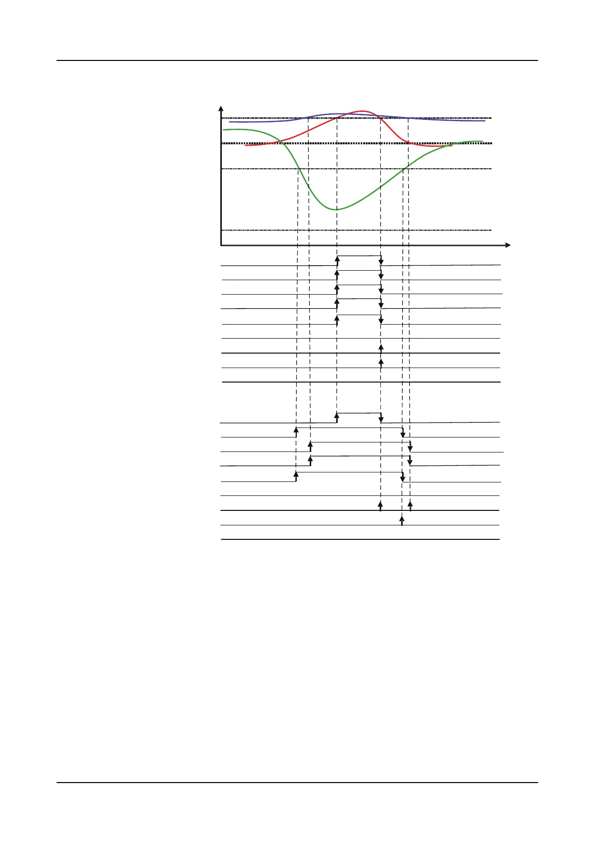
A) Three phase mode
B) Single phase mode
Figure 582: Concurrent dip and two-phase swell
10.3.5 Recorded data
Besides counter increments, the information required for a later fault analysis is
stored after a valid voltage variation is detected.
Recorded data information
When voltage variation starts, the phase current magnitudes preceding the
activation moment are stored. Also, the initial voltage magnitudes are temporarily
stored at the variation starting moment. If the variation is, for example, a two-
phase voltage dip, the voltage magnitude of the non-active phase is stored from
this same moment, as shown in
Figure 583
. The function tracks each variation-
Power quality measurement functions
1MRS757644 H
1098 620 series
Technical Manual

 Loading...


