active for the duration of the set pulse length. When activated, the additional
activation command does not extend the length of pulse. Thus, the pulse needs
to be ended before the new activation can occur.
The
Description
setting can be used for storing signal names for each output.
Each control point or SPCLGAPC can only be accessed through the LHMI control.
SPCLGAPC follows the local or remote (L/R) state if the
Loc Rem restriction
setting
is "true". If the
Loc Rem restriction
setting is "false", local or remote (L/R) state is
ignored, that is, all controls are allowed regardless of the local or remote state.
The BLOCK input can be used for blocking the output functionality. The BLOCK input
operation depends on the
Operation mode
setting. If the
Operation mode
setting is
set to "Toggle", the output state cannot be changed when the input BLOCK is TRUE.
If the
Operation mode
setting is set to "Pulsed", the activation of the BLOCK input
resets the output to the FALSE state.
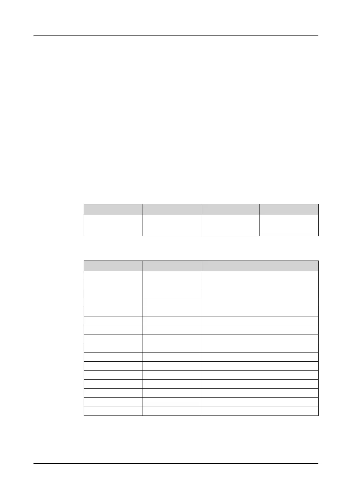
3.17.13.4 Signals
Table 197: SPCLGAPC Input signals
Name Type Default Description
BLOCK BOOLEAN 0=False Block signal for acti-
vating the blocking
mode
Table 198: SPCLGAPC Output signals
Name Type Description
O1 BOOLEAN Output 1 status
O2 BOOLEAN Output 2 status
O3 BOOLEAN Output 3 status
O4 BOOLEAN Output 4 status
O5 BOOLEAN Output 5 status
O6 BOOLEAN Output 6 status
O7 BOOLEAN Output 7 status
O8 BOOLEAN Output 8 status
O9 BOOLEAN Output 9 status
O10 BOOLEAN Output 10 status
O11 BOOLEAN Output 11 status
O12 BOOLEAN Output 12 status
O13 BOOLEAN Output 13 status
O14 BOOLEAN Output 14 status
O15 BOOLEAN Output 15 status
O16 BOOLEAN Output 16 status
Basic functions 1MRS757644 H
200 620 series
Technical Manual

 Loading...


