national grid codes. The LVRT curve can be defined accurately according to the
requirements by setting the appropriate time-voltage coordinates.
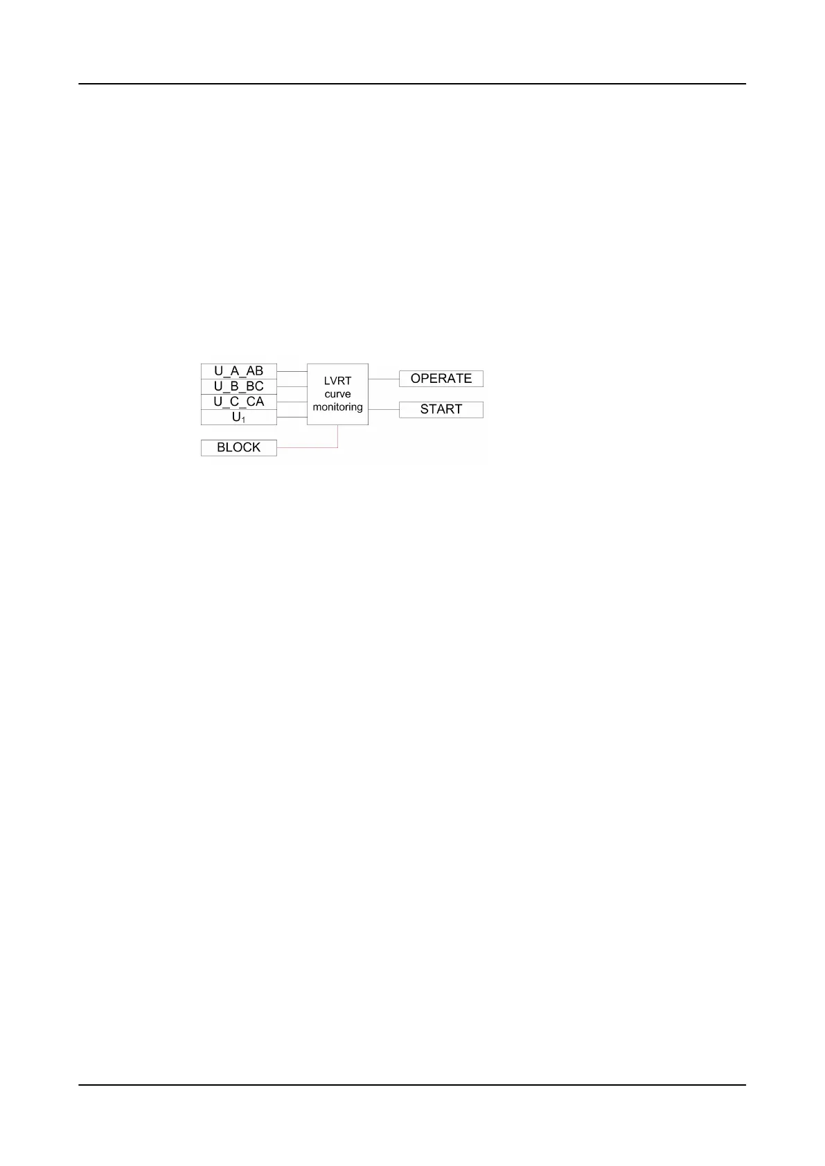
The function contains a blocking functionality. LVRTPTUV can be blocked with the
BLOCK input. Blocking resets timers and outputs.
4.5.9.4 Operation principle
The function can be enabled and disabled with the
Operation
setting. The
corresponding parameter values are "On" and "Off".
The operation of LVRTPTUV is described using a module diagram. All modules in the
diagram are explained in the next sections.
Figure 358: Functional module diagram
LVRT curve monitoring
LVRT curve monitoring starts with detection of undervoltage. Undervoltage
detection depends on
Voltage selection
setting. All selectable options are based
on fundamental frequency components.
Function uses phase-to-earth voltages when
Voltage selection
is set to “Highest
Ph-to-E” or “Lowest Ph-to-E” and phase-to-phase voltages when
Voltage selection
is
set to “Highest Ph-to-Ph” or “Lowest Ph-to-Ph”.
When the
Voltage selection
setting is set to “Highest Ph-to-E”, “Lowest Ph-to-E”,
“Highest Ph-to-Ph” or “Lowest Ph-to-Ph”, the measured three-phase voltages are
compared phase-wise to the set
Voltage start value
. If the measured value is lower
than the set
Voltage start value
setting in number of phases equal to that set
Num
of start phases
, the START output is activated.
The setting options available for
Num of start phases
are “Exactly 1 of 3”, "Exactly
2 of 3", and “Exactly 3 of 3”, which are different from conventional setting options
available in other functions. For example,
Num of start phases
is set to "Exactly
2 of 3", any two voltages should drop below
Voltage start value
within one cycle
network for the START output to activate. Even if more than two voltages drop
below
Voltage start value
, START output is not activated.
When the
Voltage selection
setting is “Positive Seq”, the positive-sequence
component is compared with the set
Voltage start value
. If it is lower than the
set
Voltage start value
, the START output is activated.
Once START is activated, the function monitors the behavior of the voltage defined
by
Voltage selection setting
with the defined LVRT curve. When defined voltage
enters the operating area, the OPERATE output is activated instantaneously. The
pulse length of OPERATE is fixed to 100 ms. START also deactivates along with
OPERATE.
Protection functions
1MRS757644 H
688 620 series
Technical Manual

 Loading...


