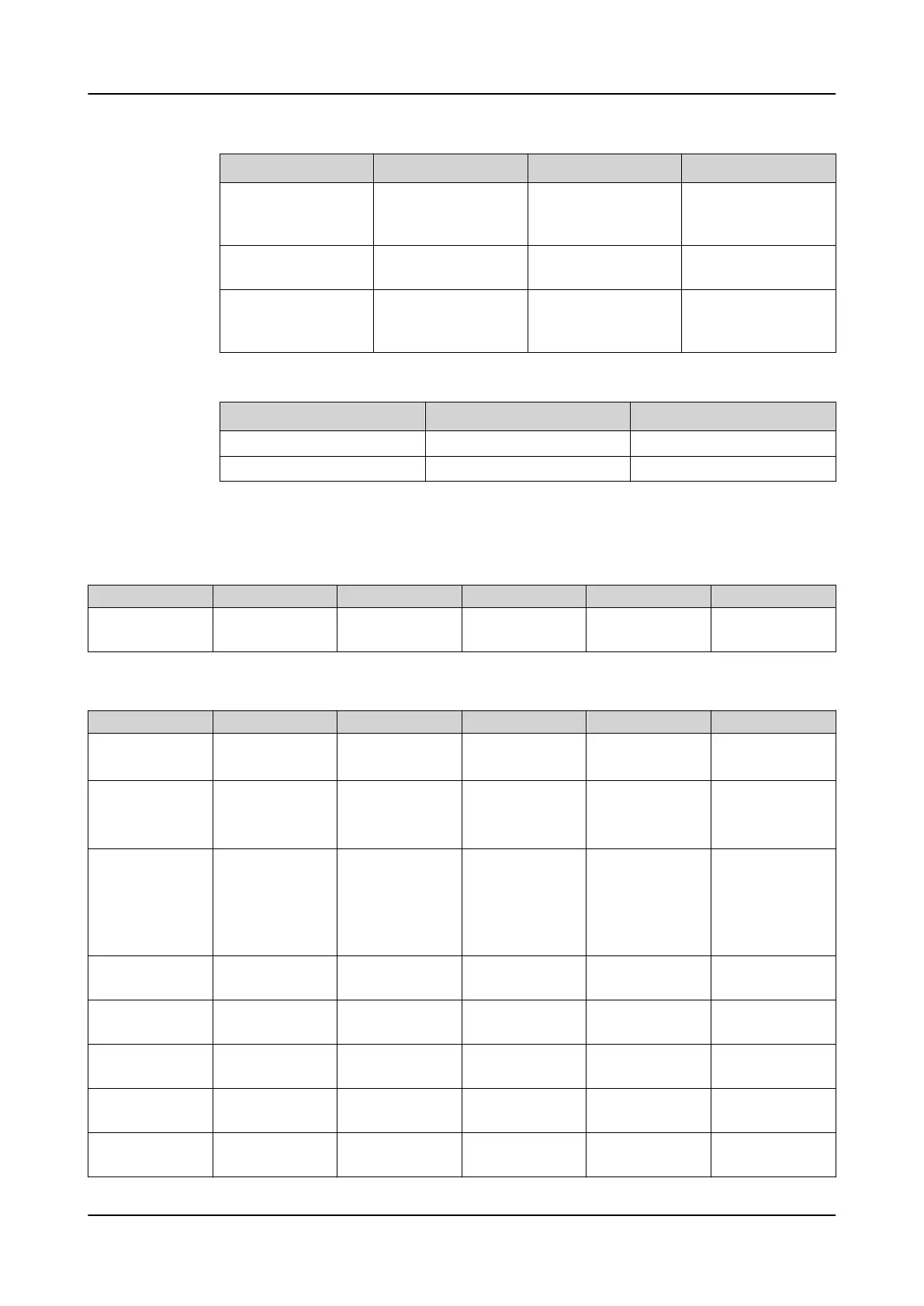
Name Type Default Description
U_A_CA SIGNAL 0 Phase-to-earth volt-
age C or phase-to-
phase voltage CA
U
1
SIGNAL 0 Positive phase se-
quence voltage
BLOCK BOOLEAN 0=False Block signal for acti-
vating the blocking
mode
Table 649: LVRTPTUV Output signals
Name Type Description
OPERATE BOOLEAN Operate
START BOOLEAN Start
4.5.9.7 Settings
Table 650: LVRTPTUV Group settings (Basic)
Parameter
Values (Range) Unit Step Default Description
Voltage start value 0.05...1.20 xUn 0.01 0.90 Voltage value be-
low which function
starts
Table 651: LVRTPTUV Non group settings (Basic)
Parameter
Values (Range) Unit Step Default Description
Operation
1=on
5=off
1=on Operation Off / On
Num of start pha-
ses
4=Exactly 1 of 3
5=Exactly 2 of 3
6=Exactly 3 of 3
4=Exactly 1 of 3 Number of faulty
phases
Voltage selection
1=Highest Ph-to-E
2=Lowest Ph-to-E
3=Highest Ph-to-Ph
4=Lowest Ph-to-Ph
5=Positive Seq
4=Lowest Ph-to-Ph Parameter to select
voltage for curve
monitoring
Active coordinates 1...10 1 3 Coordinates used
for defining LVRT
curve
Voltage level 1 0.00...1.20 xUn 0.01 0.20 1st voltage coordi-
nate for defining
LVRT curve
Voltage level 2 0.00...1.20 xUn 0.01 0.80 2nd voltage coordi-
nate for defining
LVRT curve
Voltage level 3 0.00...1.20 xUn 0.01 0.90 3rd voltage coordi-
nate for defining
LVRT curve
Voltage level 4 0.00...1.20 xUn 0.01 0.90 4th voltage coordi-
nate for defining
LVRT curve
Table continues on the next page
1MRS757644 H Protection functions
620 series
Technical Manual
693

 Loading...


