MODULE 4: POWER AND CIRCUIT BOARDS
ARCHITECT
®
RSH Service Training Guide 4-15
201532-102 FOR INTERNAL USE ONLY
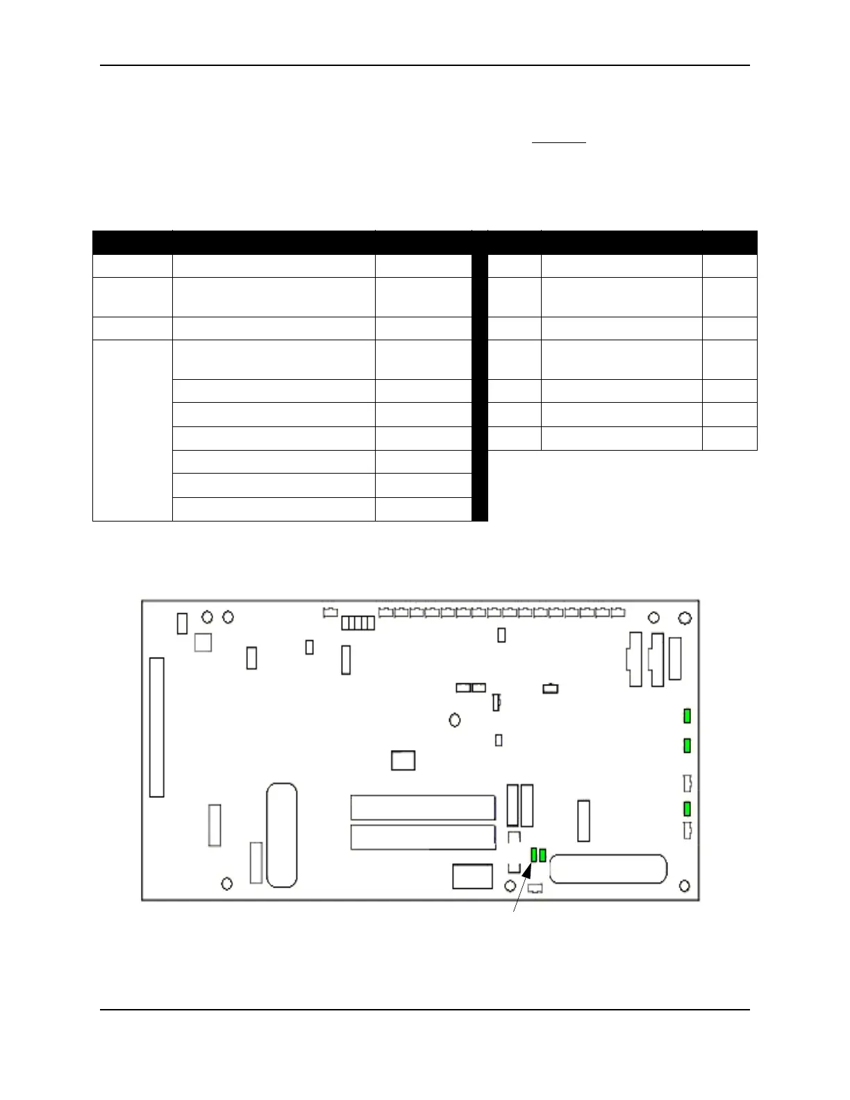
Sensor Interface Board (SIB)
The SIB supplies the power to several RSH components. In addition, it develops
two voltages 1.8VDC and
3.3VDC to use for SIB logic.
The SIB contains fuses and LEDs to assist with "Normal vs. Failure" identification during troubleshooting.
The voltage, function and state of these devices are listed in the table below:
Voltage Function Fuses LEDs Function States
+1.8VDC • Board Logic •N/A DS1 • 5VDC Power IN OK
+3.3VDC • Board Logic • F6* and F8*
DS2 • 5VDC Regulated
(DC/DC Output)
OK
+3.3VDC • Cover Interlock Sensor Boards • F10*
DS7 • 3.3VDC OK
+5VDC • RSH Bar Code Reader •F7 DS10 • 5VDC Unregulated
(PLSB/UDB LED Power)
OK
•RSH Keypad •F7
DS14 • 1.8VDC OK
• PLSB and UDBs • F9 and F5
DS16 • 1.8VDC Power Fault Fault
• Carrier Positioner Board •F1 DS18 • 3.3VDC Power Fault Fault
• Carrier Transport Sensors • F2
• Low Voltage Regulator • F3
• Input DC/DC •F4
*These fuses are not replaceable (soldered).
F10
F8
F9
F7
F6
DS18 DS16
DS7
DS14
F4 F3
F2
F5
T4:+5VDC LED
DS10
F1
TP3:+5VDC Out
T5:GND
TP1:+5VDC Unregulated
T2:GND
DS1
DS1
SIB Fuses, Test points and LEDs
DS2