Step 1 Unpack the ARMC/2 Card (and check jumper settings), Continued
Check the following jumpers:
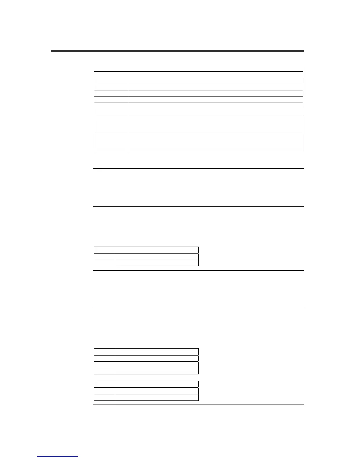
Jumper Setting
JP4 Confirm that pins one and two are open.
JP5 Confirm that pins one and two are open.
JP6 Confirm that pins one and two are open.
JP7 Confirm that pins one and two are open.
JP8 Confirm that pins one and two are open.
JP11 Confirm that pins one and two are shorted.
JP12 Confirm that pins one, two and three are open.
JP13 If your hosts system’s motherboard has support for I2C on the PCI slots,
place a short pins one and two. If not, confirm that pins one and two are
open.
JP14 If your hosts system’s motherboard has support for I2C on the PCI slots,
place a short pins one and two. If not, confirm that pins one and two are
open.
Note: The ARMC/2 cards have these two jumpers, JP13 and JP14.
JP4 and JP5 Chassis/Motherboard Power Switch
Verify that there is no jumper on JP4 and JP5. These two headers are to be used with a
cable, not a jumper.
JP6 ARMC/2 Reset Button
You can temporarily short this jumper to reset your ARMC/2 card. For normal operations,
verify that there is no jumper on JP6.
Pin Description
1 Ground
2 Reset #
JP7 and JP8 Chassis/Motherboard Reset Switch
Verify that there is no jumper on JP7 and JP8. These two headers are to be used with a
cable, not a jumper.
JP11 Flash Write Enable/Disable
You can write-protect your ARMC/2 card’s firmware so that it cannot be flashed. By
default, pins one and two are shorted so that you can flash the firmware.
Pin Description
1 VCC3
2 Write-Protect Enabled
3 Ground
Pin Description
1-2 Flash Write Enable
2-3 Flash Write Disable
Cont’d
ARMC/2 User’s Guide
6