15. Observe the positioning of the Block
Probe Cable, and gently remove it from
the Sample Cooling Assembly. Also note
the distance that the Block Probe is
inserted into the Sample Cooling
Assembly.
16. Insert the tip of the syringe (filled with
Thermal Grease) all the way into the
Block Probe hole. Inject the Grease into
the hole while slowly withdrawing the tip
to prevent the formation of air pockets.
Fill the hole with Grease (
Figure 10).
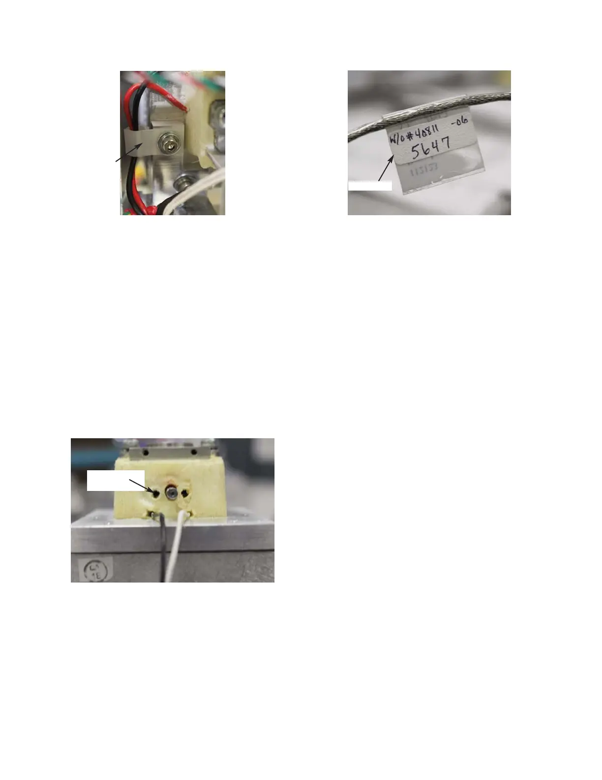
17. Record the resistance value listed on the
label of the Block Probe Cable. This
information must be entered into the
instrument’s set-up, and it will need to be
re-calibrated (
Figure 11).
18. Slowly, insert the replacement Block
Probe Cable into the Block Probe hole to
avoid causing any damage to the Probe,
and to ensure that the Thermal Grease is
properly displaced. Once the Block
Probe Cable has been fully inserted, hold
it in place until the excess Thermal
Grease has stopped oozing out of the
hole; wipe away any residual grease.
After the excess Thermal Grease has exit-
ed the Block Probe hole, the Block Probe
Cable will remain in place by itself.
Figure 11
112123RPM Rev0
(OsmoPRO Service Manual)
Page 4 of 6
Figure 9B
Figure 10
Block Probe
Hole
Cable Clip
BPC Label