112020PCRPM Rev0
(OsmoPRO Service Manual)
Page 2 of 2
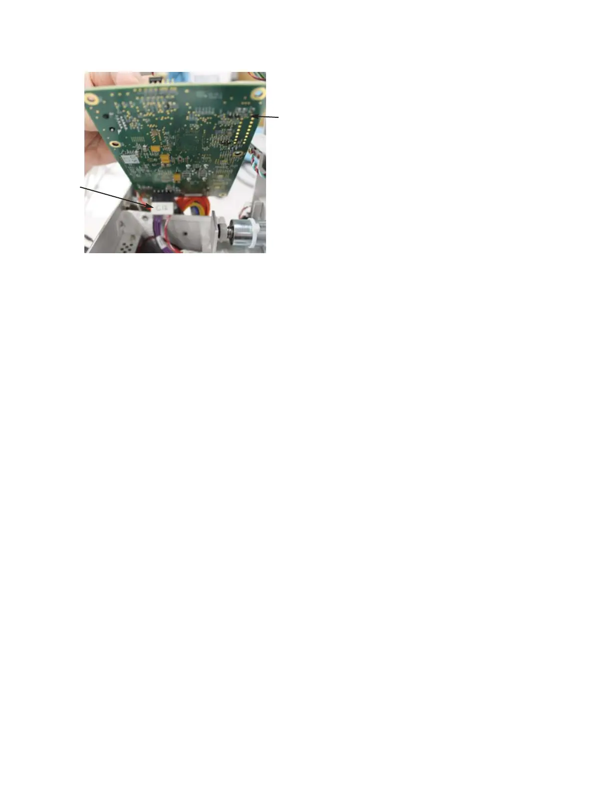
7. Plug the C12 connector into the bottom
of the replacement Control PCB.
8. Secure the Control PCB to the Power
Supply & Controls Assembly using the
six screws.
9. Plug the following Connectors into the
Control PCB: C1, C2, C5, C6, C10
& C11.
10. Attach the C3G Ring Terminal to the side
of the Power Supply & Controls
Assembly using a screw. Plug the C3
Connector into the Control PCB.
11. Secure the C10 Sample Probe Cable and
the C11 Block Probe Cable to the side of
the Power Supply & Controls Assembly
using a Cable Clamp and a screw.
12. Reverse steps one through four of the
General Disassembly Instructions
(112202PM) to reassemble the instru-
ment.
Figure 3
C12
Connector
Control PCB