17. Tighten the four socket head cap screws
that were used to mount the Sample
Cooling Assembly and the Cable Clip.
Manually raise the Movable Plate that is
secured to the Sample Probe, and lower
the Sample Well Mounting Block.
Remove the Sample Tube from the
Sample Cooling Assembly.
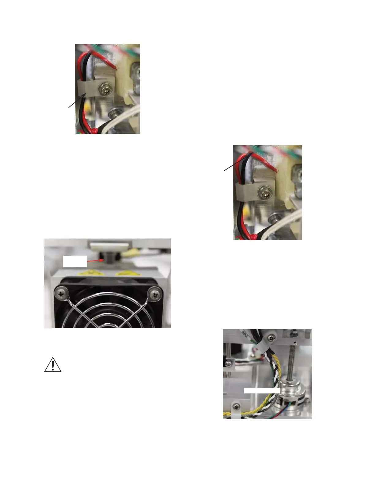
18. Dress the Thermo-electric’s wire leads
into the Cable Clip, as shown in Figure
12:
19. Secure the Block Probe Cable, the
Thermo-electric Cable and the Solenoid
Cable wire leads using the two Cable
Clamps. Be sure that there is a service
loop between the two Cable Clamps
(
Figure 13).
Figure 12
112061RPM Rev0
(OsmoPRO Service Manual)
Page 4 of 5
Thermo-
electric
Wire Leads
Service Loop
Figure 13
16. Place a Sample Tube into the Sample
Cooling Assembly. Manually raise the
Sample Well Mounting Block until the
Sample Tube is just below the Stripper
Bracket. Carefully, lower the Movable
Plate upon which the Sample Probe is
mounted until the Sample Probe enters
the Sample Tube (
Figure 11).
NOTE: THE SAMPLE COOLING
ASSEMBLY MUST BE ALIGNED
WITH THE SAMPLE PROBE. DO
NOT MOVE EITHER PART MORE
THAN REQUIRED TO COMPLETE
THE ALIGNMENT OR THE SAM-
PLE PROBE MAY BE DAMAGED.
Figure 10
Cable Clip
Figure 11
Sample
Tube