112061RPM Rev0
(OsmoPRO Service Manual)
Page 5 of 5
20. Reconnect the Sample Well Drain Tube to
the Fitting located on the Drain Tube
Adapter (
See Figure 7).
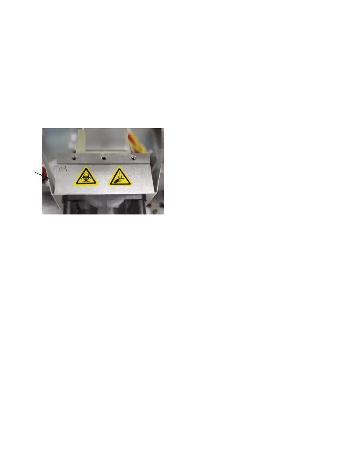
21. Mount the Cooling Fan, the Finger
Guard, and the Air-Flow Diverter to the
Cooling Assembly’s Heatsink using the
four screws and washers. The Air-Flow
Diverter must be equally spaced on the
Heatsink (
Figure 14).
22. Slide the Osmometer Module into the
instrument and mount the Osmometer
Module Mounting Bracket to the Chassis
with the four socket head cap screws and
washers.
23. Slide the Power Supply & Controls
Assembly into the Base Assembly.
24. Secure the Power Supply & Controls
Assembly to the rear of the Chassis with
the two screws.
25. Rest the instrument on its back side.
Secure the Power Supply & Controls
Assembly to the bottom of the Chassis
with the two screws. Return the instru-
ment to the upright position.
26. Attach the following Connectors on the
Cooling System Harness with their mat-
ing Connectors: A1, A2, A3 & A4.
27. Pair the following Connectors on the
Motor/Sensor Cable Harness with their
corresponding Connectors: B1, B2, B3,
B4, B6, B7, B8, B9 & B10.
28. Plug the C10 and C11 Connectors into
the Control PCB.
29. Affix the C3G Ring Terminal to the side
of the Power Supply & Controls
Assembly with a screw. Plug the C3
Connector into the Control PCB.
30. Secure the C10 Sample Probe Cable and
the C11 Block Probe Cable to the side of
the Power Supply & Controls Assembly
using a Cable Clamp and a screw.
31. Reverse steps one through twelve of the
General Disassembly Instructions to re-
assemble the instrument.
Figure 14
Air-Flow
Diverter