General Disassembly Instructions
112202PM
5. Unplug the C2 Connector from the
Control PCB (Figure 3). Remove the two
thumb screws and the Mounting Bracket
that secure Printer to the Bezel (
Figure 4).
Tools Required: Phillips Screwdrivers
(No. 1 & No. 2)
5/16” Nut Driver
Static Grounding Wrist
Strap
Warning-Hazardous Voltage
Warning – Internal components may
be damaged by static electricity
CAUTION: Improper connections
may cause damage to the instrument.
CAUTION: A discharge of static elec-
tricity from contact with the human
body or other conductor may damage
system boards or static sensitive
devices. NEVER UNPACK, TOUCH
OR HANDLE ANY PCB WITHOUT
WEARING A GROUNDING
(EARTHING) STRAP TO MINI-
MIZE YOUR STATIC DIS-
CHARGE.
Instruction:
1. Turn off the power, unplug the instrument
and remove the power cord from the
instrument.
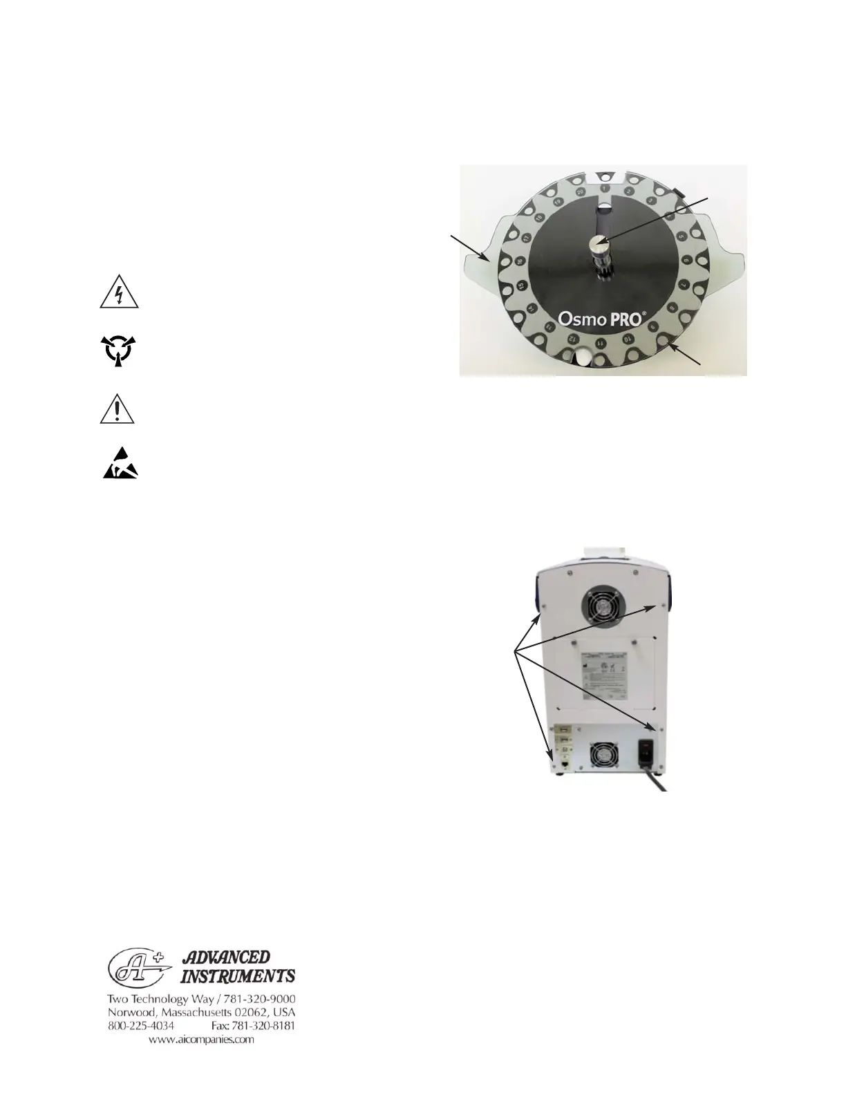
2. Remove the Turntable and the
Evaporation Cover by unscrewing the
Turntable Locking Screw (
Figure 1).
3. Remove the four screws securing the
Rear and Sides Enclosure (
Figure 2).
4. Slide the Rear and Sides Enclosure off of
the instrument.
112202PM Rev0
(OsmoPRO Service Manual)
Page 1 of 3
For additional information or technical assistance,
please contact Advanced Instruments Hot-Line
TM
Service Center (U.S. 1-800-225-4034, outside
North America +US 1-781-320-9000).
Figure 1
Evaporation
Cover
Turntable
Locking Screw
Turntable
Four Screws
on Rear
Panel
Figure 2