112202PM Rev0
(OsmoPRO Service Manual)
Page 2 of 3
9. Unplug the C3 Connector from the
Control PCB. Remove the screw that
attaches the C3G Ring Terminal to the
side of the Power Supply & Controls
Assembly (
Figure 8). Remove the Cable
with the C3 Connector from the Cable
Clamp mounted on the Chassis (
Figure 9).
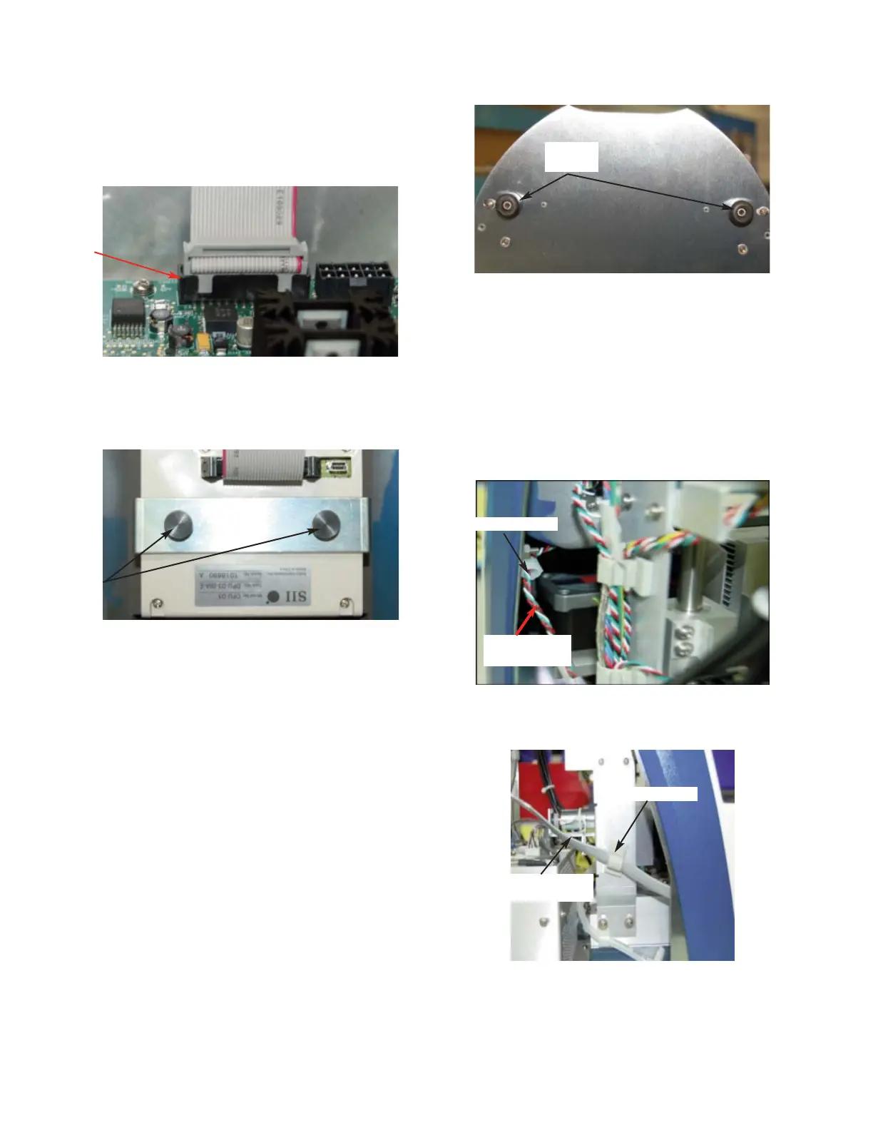
6. Rest the instrument on its back side.
Remove the two screws and washers
from the bottom of the Chassis (
Figure 5).
7. Place the instrument in the upright posi-
tion. Disconnect the PRX Connector
from the B5 Connector on the
Motor/Sensor Harness. Remove the
Proximity Sensor Cable from the Cable
Clamp (Figure 6).
8. Disconnect the C1 Connector from the
Control PCB. Remove the Barcode
Scanner Cable from the Cable Clamp that
is mounted on the Osmometer Module
(Figure 7).
Figure 3
Figure 4
Figure 5
Figure 6
Cable Clamp
Proximity
Sensor Cable
Figure 7
Barcode
Scanner Cable
Cable Clamp
Two
Thumb
Screws
C2
Connector
Two
Screws