112202PM Rev0
(OsmoPRO Service Manual)
Page 3 of 3
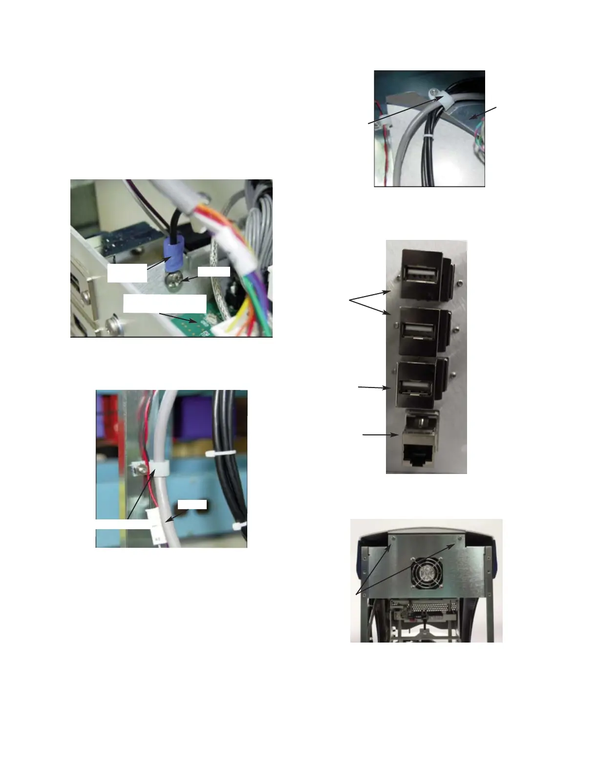
10. Remove the Cable Clamp that secures the
USB, Ethernet, and Display Cables to the
inside of the Chassis (
Figure 10). Unplug
the three USB Cables and the Ethernet
Cable from the Ports located on the
Power Supply & Controls Assembly
(
Figure 11).
11. Remove the two screws that secure the
Bezel to the Chassis (
Figure 12).
12. Carefully, lift and remove the Bezel
Assembly from the Base Assembly.
Figure 8
C3G Ring
Terminal
Power & Controls
Assembly
Figure 12
Figure 11
Figure 10
Figure 9
Cable Clamp
Cable
Cable Clamp
Chassis
Ethernet Port
USB Port 1
USB Port 2
USB Port 3
Screws
Screw