The OsmoPRO
®
Micro-Osmometer Service Manual
25
OmsoPRO Electrical Description
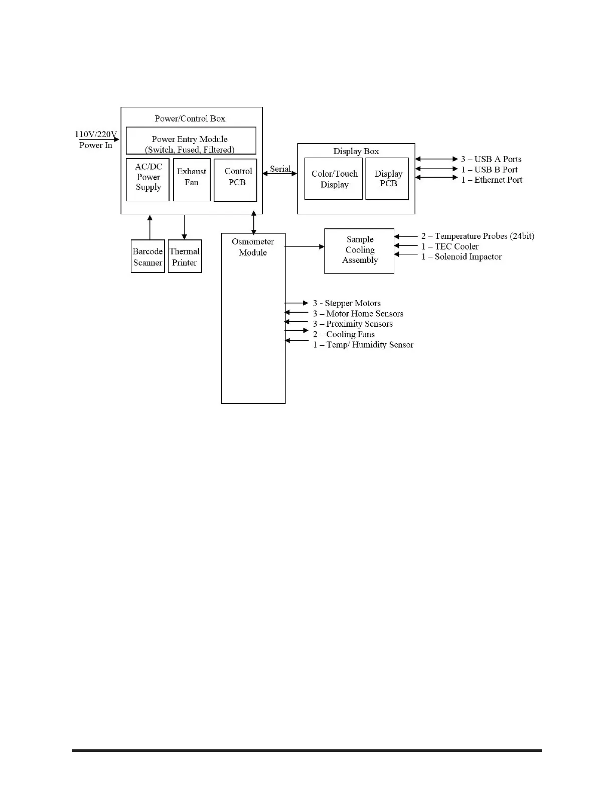
POWER SUPPLY AND CONTROL PCB ASSEMBLY, P/N 112028
The power supply and control PCB assembly is divided into lower and upper sections using a metal
shelf. The lower section contains the power entry module (PEM), a 200W AC/DC power supply and a
fan. All high voltage connections are contained in the lower section making it safe to operate the instru-
ment with either the rear door and/or cover removed.
The upper section contains the control PCB (P/N 112020) that controls all of the instruments low-level,
time sensitive operations, such as the motors, fans, optical sensors, thermo-electric chamber, solenoid,
thermal printer, barcode scanner and the high precision temperature probes. The control board utilizes
microchip micro-controller, PIC32MZ.
Bar Code Scanner Port
This port communicates to a 2D barcode scanner (Jadak FM-204) via 115 Kbps, 1 start bit, 1 stop bit
and no parity protocol. The scanner has a presentation mode that is activated when an object trips the
scanner proximity sensor. The sensor has built-in red illumination LEDs to help read barcodes in low
light conditions.
Thermal Printer Port
This port communicates to a thermal printer module (Seiko DPU-D3-00A-E) via 115 Kbps, 1 start bit, 1
stop bit and no parity protocol.