Osmometer Module Replacement
112046R
Reference: Use this instruction with replace-
ment part 112046R, and the
General Disassembly
Instructions (112202PM).
Tools Required: Phillips Screwdrivers
(No. 1 & No. 2)
Nut Drivers (1/4” & 5/16”)
9/ 64”Allen Wrench
Static Grounding Wrist
Strap
Warning-Hazardous Voltage
CAUTION: A discharge of static
electricity from contact with the
human body or other conductor may
damage system boards or static sensi-
tive devices. NEVER UNPACK,
TOUCH OR HANDLE ANY PCB
WITHOUT WEARING A
GROUNDING (EARTHING)
STRAP TO MINIMIZE YOUR
STATIC DISCHARGE.
Instruction:
1. Disassemble the instrument by perform-
ing steps one through twelve of the
General Disassembly Instructions.
2. Remove the Cable Clamp that secures the
C10 Sample Probe Cable and the C11
Block Probe Cable to the side of the
Power Supply & Controls Assembly
(
Figure 1).
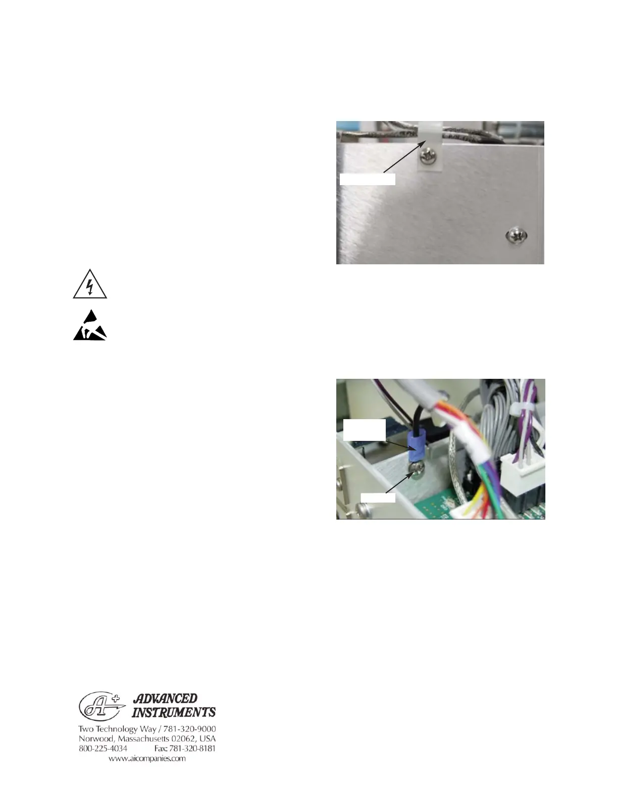
3. Unplug the C3 Connector from the
Control PCB. Remove the screw that
attaches the C3G Ring Terminal to the
side of the Power Supply & Controls
Assembly (
Figure 2).
4. Unplug the C10 and C11 Connectors
from the Control PCB.
5. Disconnect the following Connectors on
the Motor/Sensor Cable Harness from
their mating Connectors: B1, B2, B3, B4,
B6, B7, B8, B9 & B10.
For additional information or technical assistance,
please contact Advanced Instruments Hot-Line
TM
Service Center (U.S. 1-800-225-4034, outside
North America +US 1-781-320-9000).
112406RPM Rev0
(OsmoPRO Service Manual)
Page 1 of 3
Figure 1
Figure 2
Cable Clamp
C3G Ring
Terminal
Screw