The OsmoPRO
®
Micro-Osmometer Service Manual
23
OsmoPRO Mechanical Description
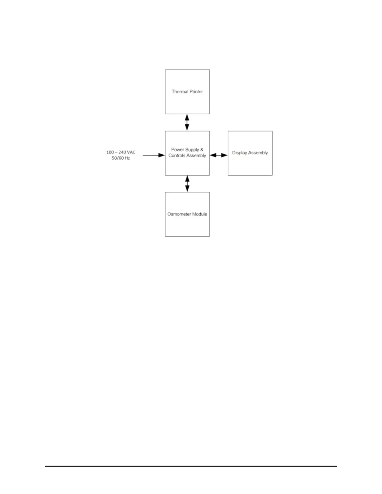
The OsmoPRO contains four major components:
Osmometer Module: This is the part of the osmometer where the test is performed. The sample probe,
cooling assembly, turntable and motors are all components of the osmometer module.
Power Supply & Controls Assembly: This component provides power to the instrument via the fused
power inlet assembly. The control PCB contains the logic necessary to perform tests and communica-
tions with the display assembly, printer and the barcode scanner. The physical USB and ethernet ports
are mounted to the power supply & controls assembly and connected to the display assembly with
cables.
Display Assembly: This assembly consists of the display PCB and the touchscreen display. It pro-
vides the graphical user interface (GUI) used to show and retrieve information pertaining to tests and the
instrument's set-up. The USB and ethernet port interfaces and cables are part of the display assembly.
Printer: The printer generates copies of test results, test statistics and basic information about the
instrument, such as the serial number, date/time and software/firmware versions.