NOTE: THE POSITION OF THE
COOLING FAN IS IMPORTANT.
PLEASE NOTE ITS ORIENTATION
BEFORE REMOVING IT FROM
THE CHASSIS.
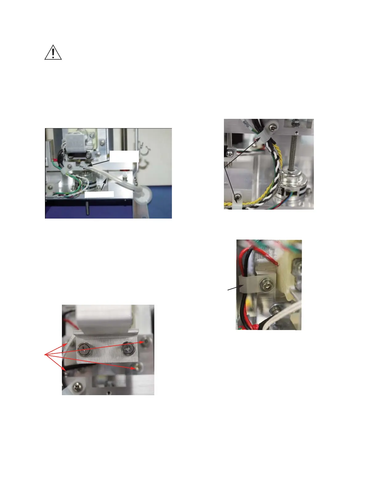
12. Disconnect the Sample Well Drain Tube
from the Fitting located on the Drain
Tube Adapter. (
Figure 7).
13. Remove the four socket head cap screws
and washers that are used to mount the
Sample Cooling Assembly to the Sample
Well Mounting Block. One of the socket
head cap screws is also used to secure a
Cable Clip (
Figure 8).
Figure 7
Figure 8
112061RPM Rev0
(OsmoPRO Service Manual)
Page 3 of 5
Drain Tube
Adapter
Drain Tube
Four Socket
Head Cap
Screws
14. Remove the Block Probe Cable, the
Thermo-electric Cable and the Solenoid
Cable from the two Cable Clamps.
Detach the Cable Clip from the Thermo-
electric’s wire leads. Carefully, lift the
Sample Cooling Assembly out of the
Osmometer Module Assembly (
Figure 9A
& Figure 9B
).
15. Loosely mount the replacement Sample
Cooling Assembly and the Cable Clip to
the Sample Well Mounting Block using
the four socket head cap screws and
washers. The Heatsink should be flush
with the Sample Well Mounting Block’s
uprights. Confirm that the Cable Clip is
positioned as shown in Figure 10:
Two
Cable
Clamps
Figure 9A
Cable Clip
Figure 9B