112061RPM Rev0
(OsmoPRO Service Manual)
Page 2 of 5
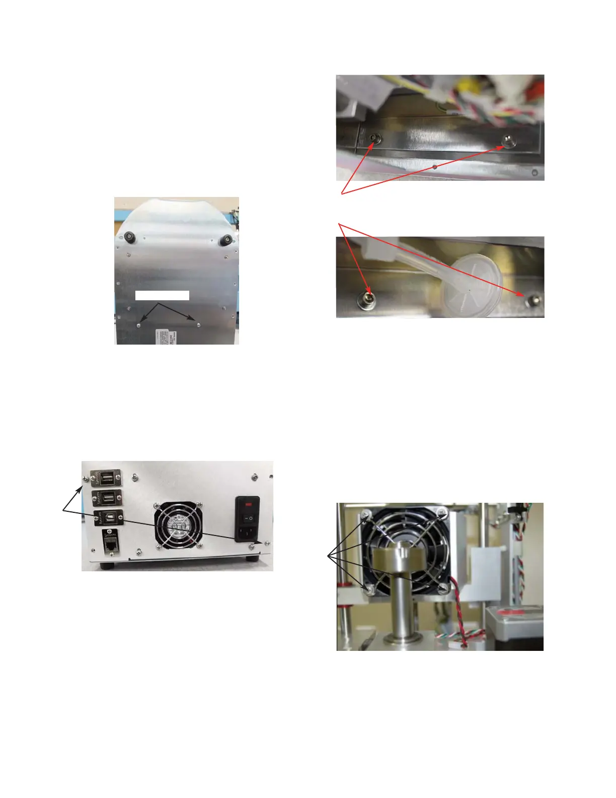
Two Screws
6. Disconnect the following Connectors on
the Cooling System Harness from their
mating Connectors: A1, A2, A3 & A4.
7. Rest the instrument on its back side.
Remove the two screws that secure the
Power Supply & Controls Assembly to
the bottom of the Chassis (
Figure 3).
8. Place the instrument in the upright posi-
tion. Remove the two screws that secure
the Power Supply & Controls Assembly
to the rear of the Chassis (
Figure 4).
9. Slide the Power Supply & Controls
Assembly out of the Base Assembly.
10. Remove the four socket head cap screws
and washers that mount the Osmometer
Module Mounting Bracket to the Chassis.
Carefully, slide the Osmometer Module
out of the instrument (
Figure 5A & Figure
5B
).
Two Screws
Figure 3
Figure 4
11. Remove the four screws and washers that
mount the Cooling Fan, the Finger Guard,
and the Air-Flow Diverter to the Cooling
Assembly’s Heatsink. It is not necessary
to remove the Cooling Fan’s wire leads
from the Cable Clamps. The Sample
Cooling Assembly can be replaced with-
out further disassembly of these parts
(
Figure 6).
Four Socket
Head Cap
Screws
Figure 5A
Figure 5B
Four
Screws
Figure 6