112123RPM Rev0
(OsmoPRO Service Manual)
Page 5 of 6
19. Loosely mount the replacement Sample
Cooling Assembly and the Cable Clip to
the Sample Well Mounting Block with
the four socket head cap screws and
washers. The Heatsink should be flush
with the Sample Well Mounting Block’s
uprights. The Cable Clip must be posi-
tioned as depicted in Figure 12:
20. Place a Sample Tube into the Sample
Cooling Assembly. Manually raise the
Sample Well Mounting Block until the
Sample Tube is just below the Stripper
Bracket. Carefully, lower the Movable
Plate upon which the Sample Probe is
mounted until the Sample Probe enters
the Sample Tube (Figure 13).
NOTE: THE SAMPLE COOLING
ASSEMBLY MUST BE ALIGNED
WITH THE SAMPLE PROBE. IN
ORDER TO AVOID ANY POTEN-
TIAL DAMAGE TO THE SAMPLE
PROBE, DO NOT MOVE EITHER
PART MORE THAN IS REQUIRED
TO COMPLETE THE ALIGNMENT.
21. Tighten the four socket head cap screws
on the Sample Cooling Assembly and the
Cable Clip. Manually raise the Movable
Plate upon which the Sample Probe is
mounted, and lower the Sample Well
Mounting Block. Remove the Sample
Tube from the Sample Cooling Assembly.
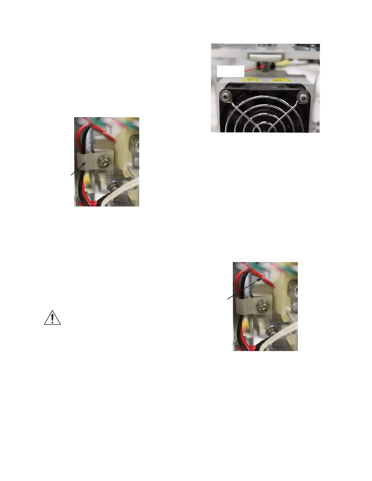
22. Dress the Thermo-electric’s wire leads
into the Cable Clip as shown in Figure
14:
Figure 12
Figure 13
Figure 14
Thermo-
electric Wire
Leads
Cable Clip
Sample
Tube