ADAM-6200 User Manual 102
Internal Flag for Logic Cascade and Feedback
Logic Cascade
Using internal flag as interface, you can combine different logic together to form
a new single logic rule which can play more complex logic architecture. You can
combine logic rules on the same module, or even on different modules. Please
refer to example below to understand how the internal flag works.
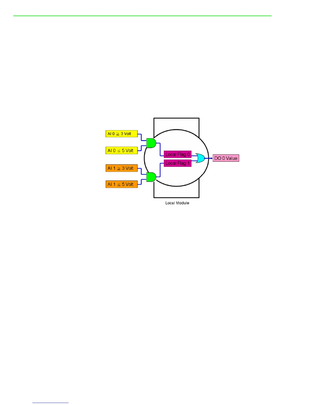
Local Logic Cascade
Here, we take one simple example to describe the logic cascade. We use two
analog input channels (channel 0 and channel 1) of ADAM-6217 to measure
signal from sensors. As long as either of the two input channel read voltage
between 3 ~ 5 Volt, digital channel 0 should generate logic high value. Other-
wise, the digital channel 0 should generate logic low value. The logic architec-
ture will look like as below.
In order to implement this logic architecture, we need to use three logic rule and two
internal flag to achieve this. Refer to the following diagrams to see how to configure
the three logic rules.