89 ADAM-6200 User Manual
Chapter 4 System Configuration
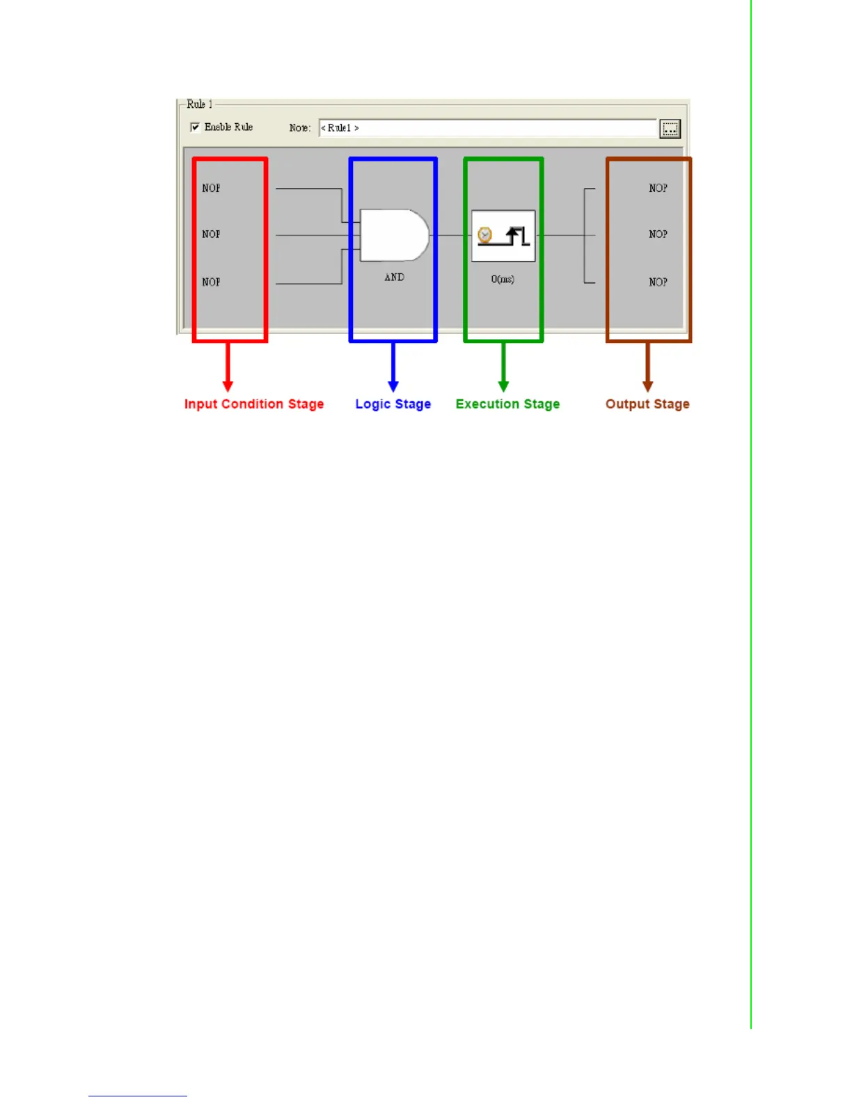
4.3.5.3 Basic Logic rule programming
Input Condition stage
The Input Condition stage is a logic condition decision for the input data.
The decision result will be logic True or False, sending to the Logic stage for logic
operation. Take analog input mode as example, you can define the condition as if the
analog input value is greater than a specific value (the limit). So when the input value
becomes greater than the limit, the input stage will transfer True to the Logic stage.
Otherwise, it will transfer False to the Logic stage.
When you click the Input Condition stage icon, you should see a dialog window simi-
lar as below. You can choose the input mode by the Mode combo box. The default
mode is NoOperation, meaning there is no input condition. You can choose local ana-
log input channel (AI), local digital input channel (DI), local counter input channel
(DI_Counter), local frequency input channel (DI_Frequency), internal timer (Timer),
internal flag (AuxFlag) , local digital output channel (DO) and internal counter (Coun-
ter) as the input mode. After you choose the appropriate input mode and complete all
related setting, click the OK button. That Input Condition stage icon will change its
pattern to present the current condition. We will describe each mode in more detail
below.