ADAM-6200 User Manual 110
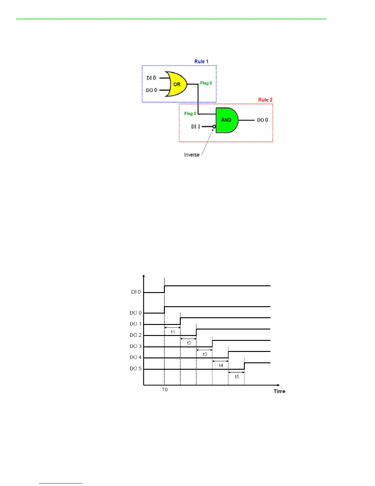
Now, we can use GCL logic to achieve the same control operation. Two logic rules
are used. The complete logic architecture is shown as below.
After you load the example project file, you can find that it uses rule 1 and rule 2. One
output of rule 1 and one input of rule 2 are assigned to the same internal flag: Flag 0.
This can combine 2 or more logic rules together, that we call it Logic Cascade. We
have configured the condition for DI 1 input as False, so the DI input value is inverted
before entering the AND operator of rule 2. The GCL logic architecture is similar to
the PLC ladder diagram.
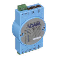
3. Sequential Control (Turn On in Sequence and Remain On)
In this kind of application, several digital outputs will be activated in sequence and
latch their values. In the example project we provide, DO 0 ~ DO 5 will sequentially
be controlled to change their status. The time chart for this application can be shown
as below:
(Turns On in Sequence and Remains On)