EasyManua.ls Logo

Advantech ADAM-6256 User Manual

Advantech ADAM-6256
192 pages
To Next Page IconTo Next Page
To Previous Page IconTo Previous Page
Page #117 background imageLoading...
Page #117 background image
111 ADAM-6200 User Manual
Chapter 4 System Configuration
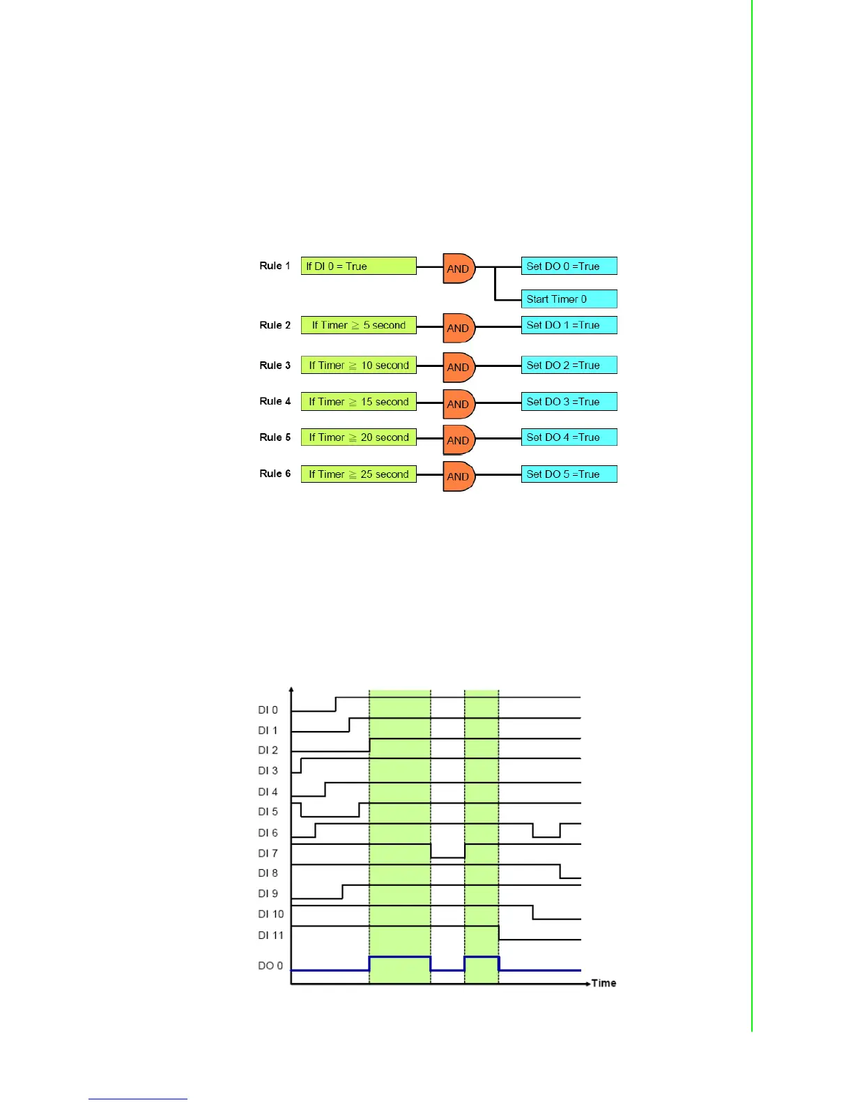
In the example project, DI 0 is used as a trigger to start the sequential control action.
Therefore, when DI 0 turn to logic high (at the moment T0), DO 0 will also change to
logic high immediately. Then, DO1 ~ DO5 will sequentially be activated to logic high
after a specific time interval. You can decide the time interval t1 ~ t5 (They can be dif-
ferent values). In this example project, t1 ~ t5 are all 5 seconds.
We can use 6 logic rules and 1 internal timer for this GCL application. In the first logic
rule, DI 0 is used to trigger Timer 0 and DO 0. Since the timer has been triggered, it
will start counting time and DO 1 ~ DO 5 will be activated after a specific amount of
time has elapsed.. The GCL architecture can be shown by as below:
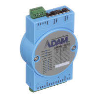
4. Multiple DI to control one DO (12 DI to 1 DO)
In many applications, only when multiple digital inputs are logic high (related condi-
tions are all satisfied), digital output status will become logic high. In the example
project we provide, only when DI 0 ~ DI 11 are all logic high at the same time, the DO
0 will become logic high. The time chart of this application can be shown as below.
The green band area indicates the moment that all 12 DI are logic high, thus DO 0
will be logic high. For other time interval, there is at least one DI channel whose value
is not logic high, so DO 0 value is logic low.

Table of Contents

Question and Answer IconNeed help?

Do you have a question about the Advantech ADAM-6256 and is the answer not in the manual?

Advantech ADAM-6256 Specifications

General IconGeneral
Digital Input Channels16
Digital Output Channels16
Communication InterfaceEthernet
Input Voltage10 to 30 VDC
ProtocolsModbus RTU
Storage Temperature-20°C to +70°C
Humidity10 to 95% RH

Summary

Chapter 1 Product Overview

1.2 Feature Highlights

Key features of the ADAM-6200 series, including installation, IT integration, and management.

Chapter 2 Product Specifications

2.2 Analog Input Module (ADAM-6217)

Details the specifications for the ADAM-6217 analog input module.

2.3 Analog Output Module (ADAM-6224)

Details the specifications for the ADAM-6224 analog output module.

2.4 Digital Input/Output Modules (ADAM-6250/6251/6256)

Details specifications for ADAM-6250, 6251, and 6256 digital I/O modules.

Chapter 4 System Configuration

4.3 Configure ADAM-6200 with ADAM.NET Utility

Guides users on configuring the ADAM-6200 module using the ADAM.NET Utility.

4.3.3 I/O Configuration

Details how to configure individual I/O channels for specific modules.

4.3.5 GCL

Introduces the Graphic Logic Condition (GCL) feature for standalone control.

Appendix A I/O Modbus Mapping Table

Appendix B ADAM-6200 ASCII Commands

Appendix C REST for ADAM-6200

Related product manuals