91 ADAM-6200 User Manual
Chapter 4 System Configuration
Local Analog Input Channel (AI)
1. After you choose AI as input mode, select the channel by the Channel combo
box.
2. In the Operation area, you can define the input condition operation. Select the
analog input type by the Type combo box. There are two input types you can
choose for analog input: If you select Channel Value, the current value of the
selected analog input channel is used as input for condition. If you select Devia-
tion, the deviation (Dividing difference between present sample value and previ-
ous sample value by the total range value) of the selected analog input channel
is used as input for condition.
3. Select the appropriate condition for that input channel by the Condition combo
box and the Value text box. Refer to the examples in the table below to see how
to define analog input condition:
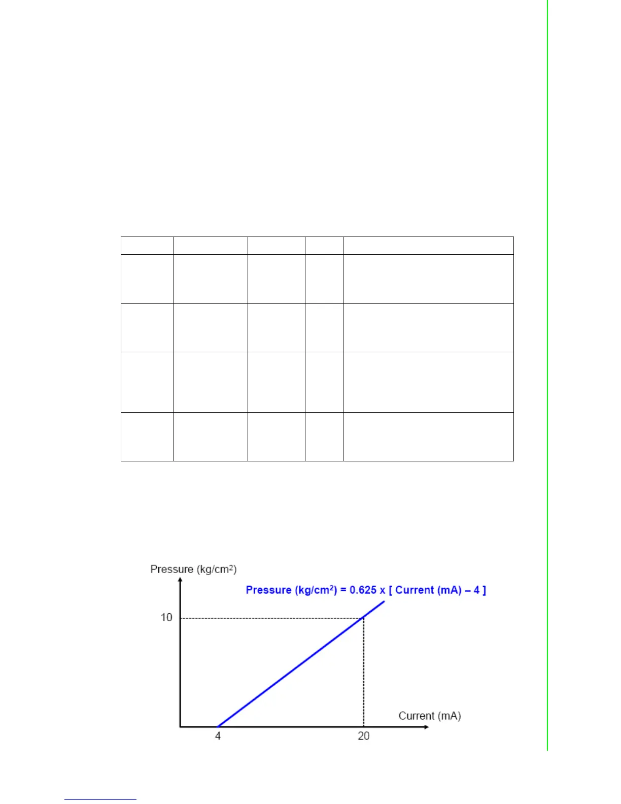
The analog input will read voltage (or current) from the channel we specified.
Usually, the voltage (or current) value can represent the real-world physical unit value
(we call it engineer unit value) and there is linear relationship between the voltage (or
current) value and the engineer unit value. For example, the current and the engineer
unit value have linear relationship as shown below:
Channel Type Condition Value Description
0 Channel value >= 5
If the value of analog channel 0 is more
than or equal to 5, the condition result
is logic True. Otherwise, the condition
result is logic False.
2 Channel value = 3.2
If the value of analog channel 2 equals
to 3.2, the condition result is logic True.
Otherwise, the condition result is logic
False.
3 Channel value <= 1.7
If the value of analog channel 3 is less
than or equal to 1.7, the condition result
is logic
True. Otherwise, the condition result is
logic False.
5 Deviation N/A 20
If the deviation of analog channel 5 is
greater than 20%, the condition result
is logic True. Otherwise, the condition
result is logic False.