3.7 Counterbalance in 4 cylinder engines
3.7.1 Removing and disassembling counterbalance unit
Procedure
1.
Remove the oil sump.
2.
Disconnect the lubricating oil pipe of the counterbalance unit.
3.
Remove the counterbalance unit. Take care of any shims.
4.
Loosen the locking screws and press out the shafts in the direction of the locking screws. Remove
the counterweights and thrust washers.
5.
Clean all parts.
3.7.2 Reconditioning counterbalance unit
Procedure
1.
Check the shafts, gear wheels and bushings for wear and damage.
2.
Change both counterweights as a complete unit, if one of the gear wheels is damaged.
The gear wheels are not available separately as a spare part.
3.
Remove the old bearing bushings with a suitable drift, if necessary.
Before removing the bearing bushings, mark the position of the bushing oil groove on the
counterweight.
4.
Press in new bearing bushings in the correct position.
5.
Ream the bushings to a correct dimension.
6.
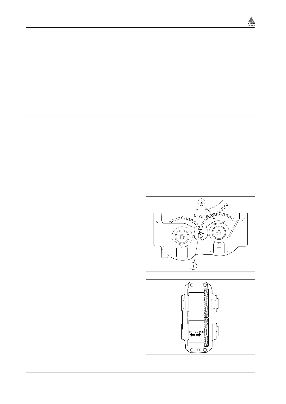
Fit the weights in the body, see for the notch
markings.
The gear wheel with two notch marks run
against the crankshaft and need to be fitted
highest there fore.
7.
Insert the shafts.
Remember the thrust bearings.
8.
Apply thread lock fluid (for example Loctite
270) to the locking screws, and lock the
shafts.
Fig. 57
9.
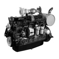
Check that the tooth backlash is 0.05 - 0.25
mm and that the end float is 0.1 - 0.3 mm.
Fig. 58
3. Maintenance
3-36 4th Generation Engines
8370 79492