4.
Turn the cylinder head over and knock out
the valve and valve seat ring.
5.
Clean the valve seat ring location.
6.
Cool the new valve seat ring in liquid
nitrogen until it stops bubbling, or
alternatively put it in dry ice.
7.
Fit the valve seat ring with a drift. Machine
the seat surface.
NOTE: Where necessary, standard size seats
can be replaced by inserts with a larger outer
diameter.
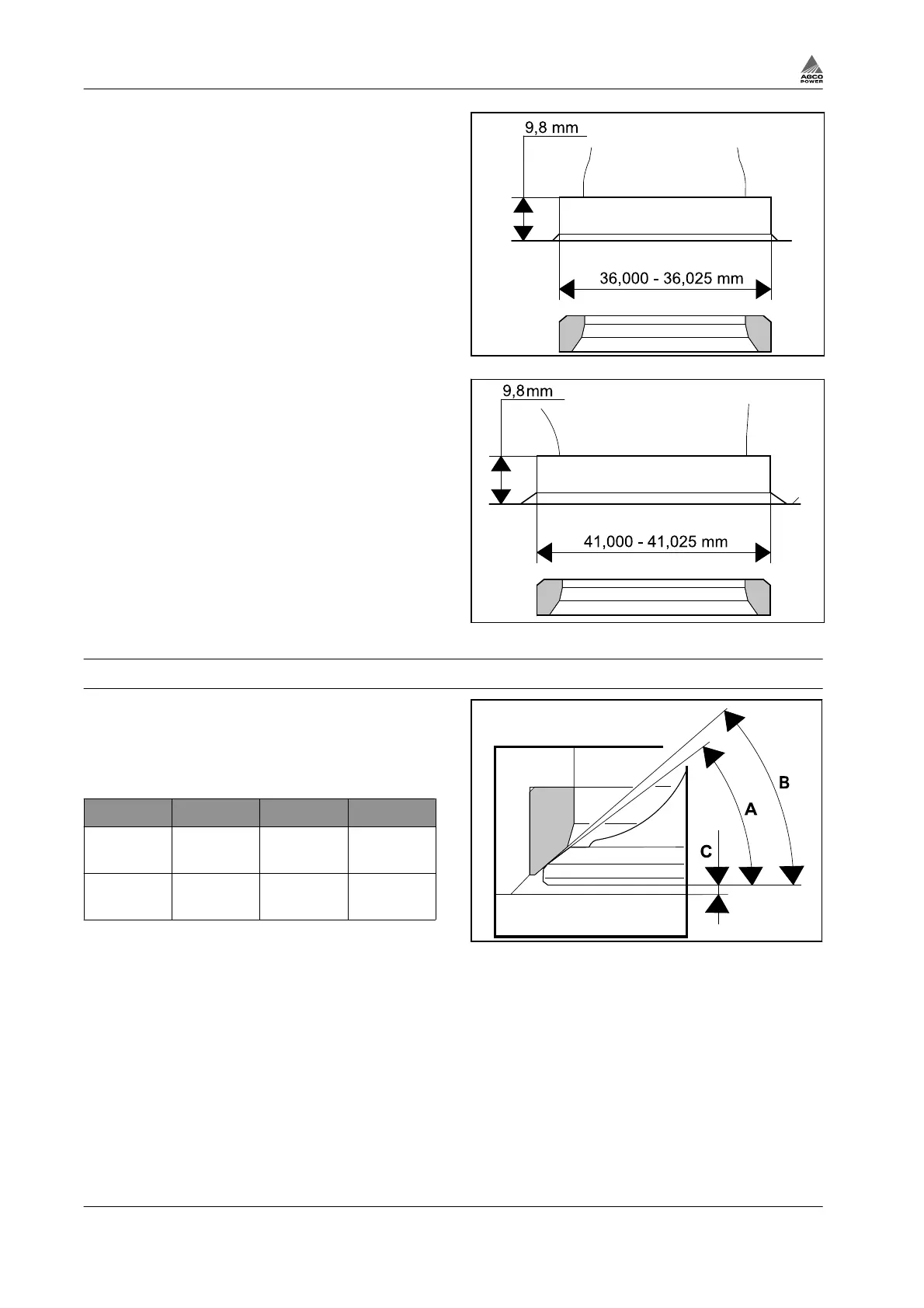
Fig. 23 Exhaust
Fig. 24 Inlet
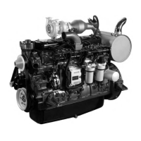
3.3.7 Grinding valves
In order to make sure that there is a proper seal
around the valves, there is a difference in the
sealing surface angles. There is there fore a very
narrow sealing surface which seals good even
after extended running.
A B C (mm)
Inlet 35°-20' 35°+20' 0.8±0.05
(max. 2.20)
Exhaust 45°-20' 45°+20' 0.6±0.05
(max. 2.20)
Fig. 25
Procedure
1.
Grind the damaged valve disc with a valve refacer.
Adjust angles to 45°±20' for exhaust valves and 35°±20' for inlet valves.
2.
The valve must be discarded, if the edge of the valve head is less than 1.5 mm after it has been
ground, or if the valve stem is bent.
3.
Grind the end of the valve stem, if necessary.
4.
Lap the valves with lapping paste.
5.
Check the contact surface with marking paint.
6.
Clean the cylinder head and valves of any remaining lapping paste.
3. Maintenance
3-18 4th Generation Engines
8370 79492