(5) Cooling pump
(6) Actuator
(7) Engine control unit
The cooled exhaust gas recirculation system (EGR) used on some AGCO POWER engines is controlled by
electronic engine control unit (ECU). Part of exhaust gases is led from exhaust manifold (1) through EGR
valve (2) to EGR cooler (3) where they are cooled with engine coolant. The cooled exhaust gas is mixed
with fresh intake air in intake manifold (4) before it flows to combustion chamber.
The cooled EGR system decreases the temperature in combustion chamber, which in turn results as lower
nitrogen oxide (NOx) emissions.
1.3.11.2 EGR cooler
The EGR cooler cools down the exhaust gases. The cooler is capable to decrease exhaust gas temperature
even with 50%.
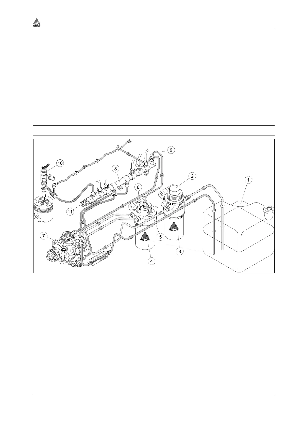
1.3.12 Fuel system
Fig. 18 Parts of fuel system, example construction
(1) Fuel tank
(2) Hand pump
(3) Pre-filter
(4) Fuel filter
(5) Fuel temperature sensor
(6) Fuel pressure sensor
(7) High-pressure pump
(8) Rail
(9) Overflow valve
(10) Injector
(11) Pressure sensor
Engines are equipped with common rail system which is controlled by electronic control unit (ECU).
Fuel is drawn from the tank via the pre-filter, through the main fuel filter to the high pressure pump. From
the high pressure pump, fuel is pumped up into the rail. This high pressurized fuel is lying in a high
pressure pipe where it is controlled and injected through electronic injectors that are controlled by EEM4.
The injection is optimized in terms of emissions, efficiency and operation noise and takes place in four
steps (maximum). Excess fuel returns from the injectors and pressure regulating valves of the high
pressure pump and rail back to the fuel tank.The overflow pipe from the filter helps the bleeding of the
system.
The fuel is diesel fuel according to the norm EN 590:2009 and it must be clean and free from water after
storage (see fuel quality requirements).
1. Introduction
4th Generation Engines 1-21
8370 79492