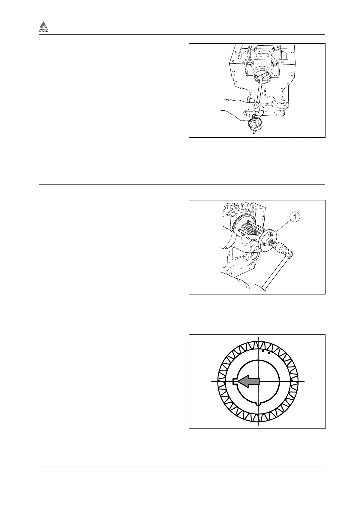
4.
Measure the I.D. with a dial gauge which has
been zeroed to the dimensions given in point
2.
With this method the indicator shows the
actual bearing clearance.
Measure at several points in case the worn
bearing housing is not round.
5.
Grind the bearing journals on the crankshaft,
if needed.
The maximum bearing clearance for main
bearings is 0.18 mm and 0.14 mm for
connecting rod big-end bearings with new
bearing shells.
Refer to the specifications for the correct
undersize and the corresponding bearings.
Fig. 38
3.5.3 Changing crankshaft gears
Procedure
1.
Apply puller 9052 48800 to the crankshaft
gears and pull off both gears.
2.
98-engine: Break the crankshaft gears using
for example a grinder.
a) Grind the gears enough for breaking.
b) Hit the gears apart with a chisel.
c) Do not damage the crankshaft!
Fig. 39
(1) Puller 9052 48800
3.
Clean the seat on the crankshaft for example with a wire brush.
4.
Heat the new gears to 220 - 250°C.
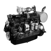
5.
Assemble the gears onto the shaft.
a) Note the position of the key and make
sure that the aligning marks on the front
gear are visible.
b) Set the crankshaft key into the angular
key slot.
6.
Let the gears cool.
Fig. 40
3. Maintenance
4th Generation Engines 3-27
8370 79492