3.10.3 Assembling and fitting lubricating oil pump
Procedure
1.
Fit the gear wheels to the pump body. Fit the cover using a new gasket. Partly tighten the screws.
Rotate the pump shaft and tap the side of the cover gently until it reaches the position in which the
shaft rotates most freely. Tighten the screws and check that the shaft still rotates freely.
2.
Fit the drive gear onto the shaft. Apply thread sealer Loctite 242 onto the nut threads and tighten the
nut to 60 Nm. Remember the washer under the nut.
3.
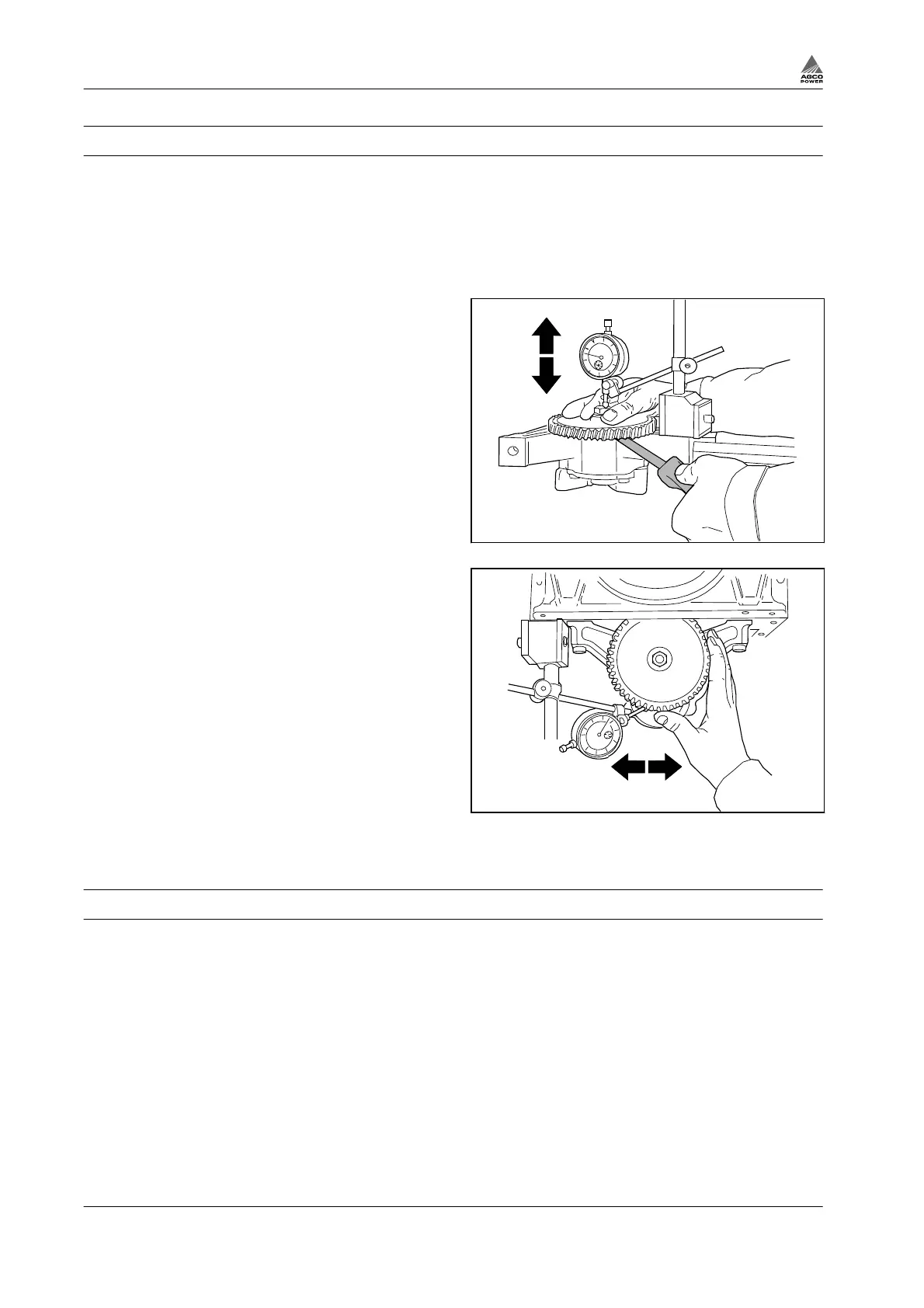
Fasten the oil pump in a vice and check the
end float between gear and pump housing.
The clearance, which should be 0.03 - 0.11
mm, is adjusted by the number of gaskets
between the cover and the body.
4.
Fit the oil pump.
Fig. 75
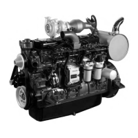
5.
Check the tooth backlash against the
crankshaft gear.
NOTE: When measuring the tooth backlash,
the engine should be the correct way up as
the crankshaft bearing clearance affects the
tooth backlash.
The clearance is adjusted with shims
between the pump body and the cylinder
block. One shim increases/decreases the
backlash by about 0.07 mm.
6.
Connect the suction and pressure pipes
together with new seals.
7.
Apply thread sealer Loctite 242 to oil sump
bolts (engines with steel sump). Fit the oil
sump and fill in the lubrication oil.
Fig. 76
3.10.4 Piston cooling nozzles
The engines with high output are fitted with piston cooling nozzles. The cooling nozzles can be removed
after the oil sump is removed. The nozzles have a valve with an opening pressure of 2.3±0.25 bar.
3. Maintenance
3-46 4th Generation Engines
8370 79492