12.
Tighten the valve cover to correct torque value.
3.13.3.3 Removing the injectors (CRI2_16)
Procedure
1.
Clean the high-pressure pipes, valve cover(s)
and surroundings.
2.
Remove the injector fixing clips.
3.
Remove the overflow pipe.
4.
Remove the high-pressure pipes.
5.
Plug plastic covers into all the connection
points.
6.
Remove the rubber covers and injector wires
from the valve cover.
7.
Remove injector flanges from the valve cover
and frame.
8.
Open the valve cover screws and remove
the valve cover.
9.
Open the frame mounting screws (camshaft
side).
10.
Open the injector fastener screws and
remove the fasteners.
11.
Remove the injector.
Tilt the frame towards the inlet manifold so
that the injectors can be lifted out.
12.
Remove the injector seal ring from the
cylinder head if it has not been removed with
the injector.
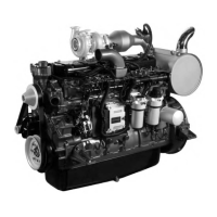
Fig. 106
(1) Injector fixing clip
(2) Overflow pipe
(3) High-pressure pipe
(4) Rubber cover
(5) Injector wiring
(6) Injector flange
(7) Frame mounting screw
(8) Fastener
3.13.3.4 Fitting the injectors (CRI2_16)
Procedure
1.
Clean and if necessary straighten the injector seat on the cylinder head with reamer 9120 85400.
2.
Replace the injector seal rings.
3.
Replace the injector flange O-rings.
4.
Lubricate the O-rings.
5.
Install the injectors on the cylinder head.
6.
Tighten the fastener screw to 28 Nm.
7.
With the frame in position and install the
injector flanges.
8.
Tighten the frame and flange screws in turn
so that the injector is correctly centered to
the flange.
9.
Install the valve cover with a new gasket.
10.
Thread the valve cover flanges into position.
11.
Tighten the valve cover and flange screws in
turn so that the injector is correctly centered
to the flange.
12.
Thread the injector rubber covers into
position.
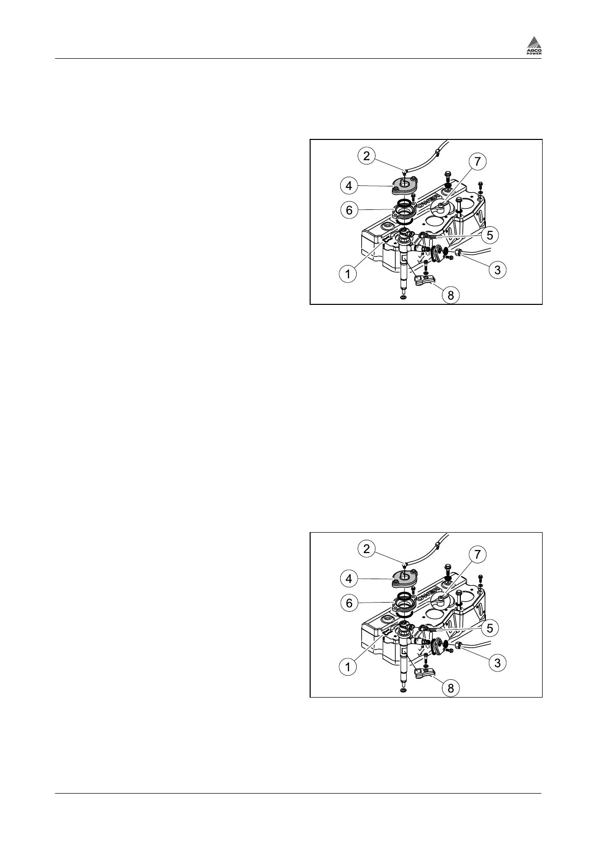
Fig. 107
(1) Injector fixing clip
(2) Overflow pipe
(3) High-pressure pipe
(4) Rubber cover
(5) Injector wiring
3. Maintenance
3-64 4th Generation Engines
8370 79492
 Loading...