3.7.3 Fitting counterbalance unit
Procedure
1.
Fit the tension pins to the cylinder block.
2.
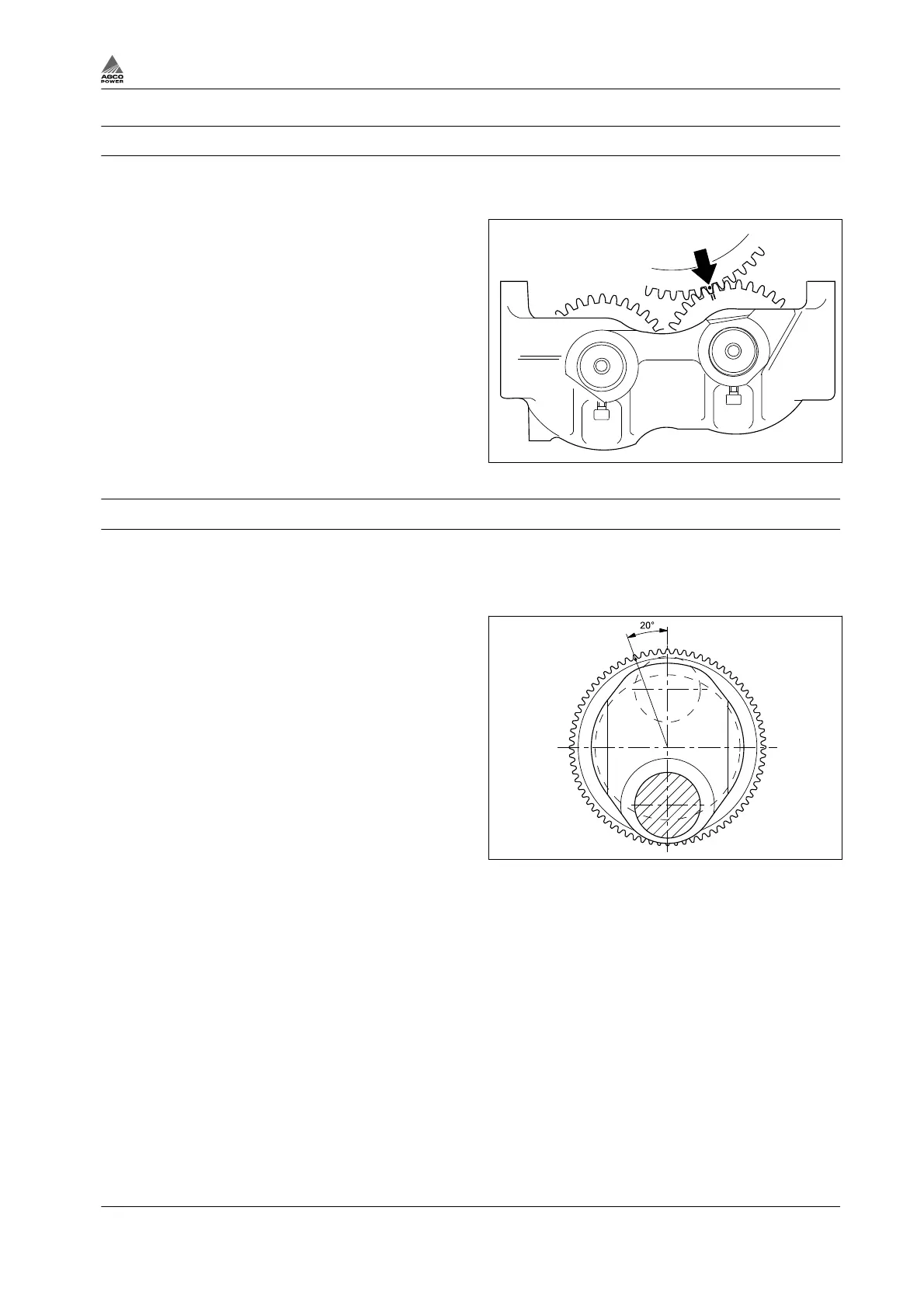
Turn the crankshaft and weights so that the
markings correspond, and lift the unit into
place.
3.
Tighten the screws to 60 Nm. Check that the
tooth backlash between the crankshaft and
counterweight is 0.1 - 0.3 mm. The backlash
can be increased by placing 0.2 mm-thick
shims (order number 8361 19920) between
the cylinder block and balancer unit body.
One shim (0.2 mm) changes tooth backlash
by about 0.07 mm.
4.
Fit the lubricating oil pipe using new seals.
5.
Fit the oil sump.
Fig. 59
3.7.4 Changing crankshaft gear rim
Procedure
1.
Mark the position of the gear rim on the shaft.
2.
Heat the gear rim with a welding torch and drive the gear rim off using a suitable drift.
3.
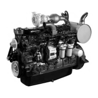
Heat the new gear rim to maximum 250°C.
NOTE: The picture shows a rear view of the
crankshaft and no. 2 cylinder big-end bearing
journal.
4.
Fit the gear rim with the chamfer facing the
crankshaft flange, and with the teeth
according to markings or according to the
figure.
5.
Tap the gear rim down and leave the gear
rim to cool.
Fig. 60
3. Maintenance
4th Generation Engines 3-37
8370 79492