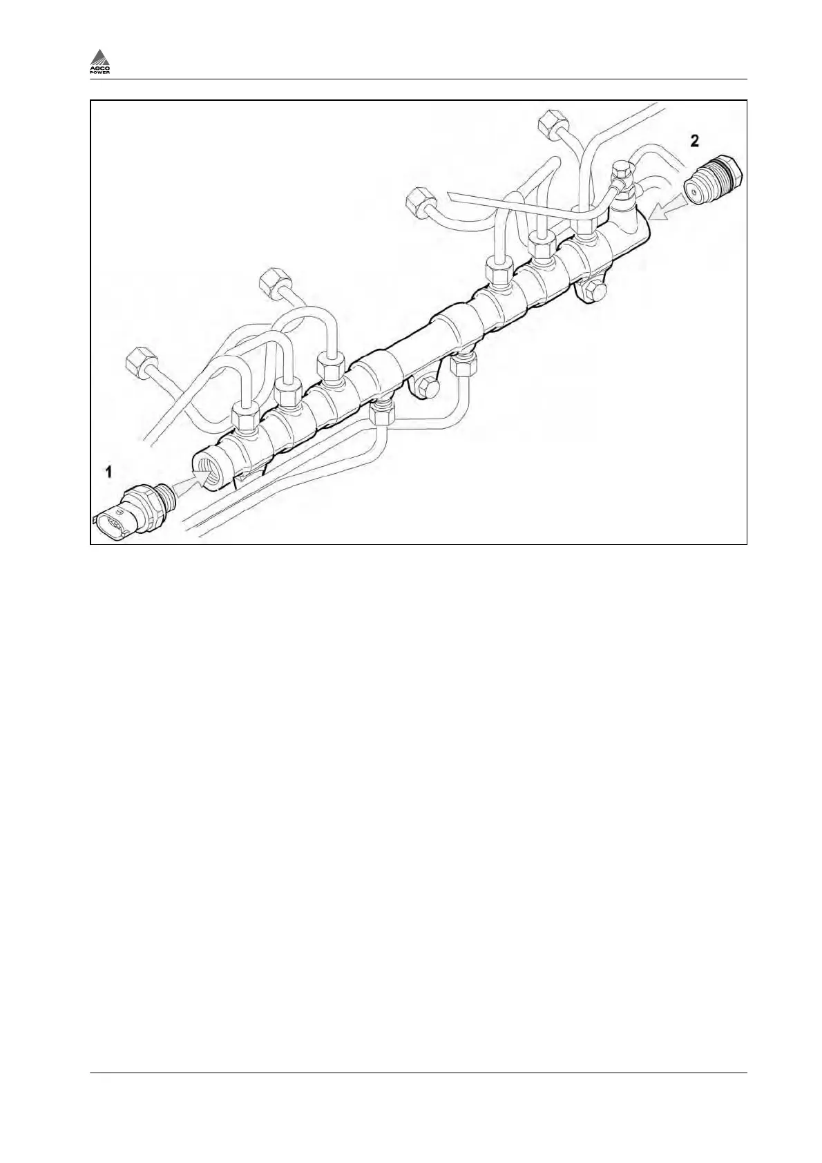
Fig. 112
(1) Pressure sensor (2) Shut-off valve
The rail is attached to the intake manifold. Turn the main switch to OFF position before handling the rail.
Clean the rail and its surroundings carefully. Prevent fuel from leaking to the ground. Insert plugs where
fuel connectors have been removed.
The pressure sensor (1) and shut-off valve (2) will be delivered as spare parts for the rail. These parts can
be changed while the rail is in position. Alternatively, the complete rail can be replaced.
Pressure Sensor
RDS, Order Number 8370 79599
1 Disconnect the electrical connector before loosening the sensor.
2 Clean the sealing surface and thread of the rail.
3 Check the condition of the end sealing surface of the pressure sensor. Radial scratch is not
permissible.
4 Lightly lubricate the sensor thread and sealing surface.
5 Tighten the sensor in place to a torque of 70 Nm.
6 Connect the electrical connector.
Shut-Off Valve
DBV, Order Number 8370 79433
1 Clean the sealing surface and the thread of the rail.
2 Check the condition of the end sealing surface of the shut-off valve. Radial scratch is not permissible.
3 Lightly lubricate the valve thread, sealing surface and O-ring.
4 Tighten the valve in place to a torque of 100 Nm.
3. Maintenance
4th Generation Engines 3-67
8370 79492