2.
Check for cracks and other damage.
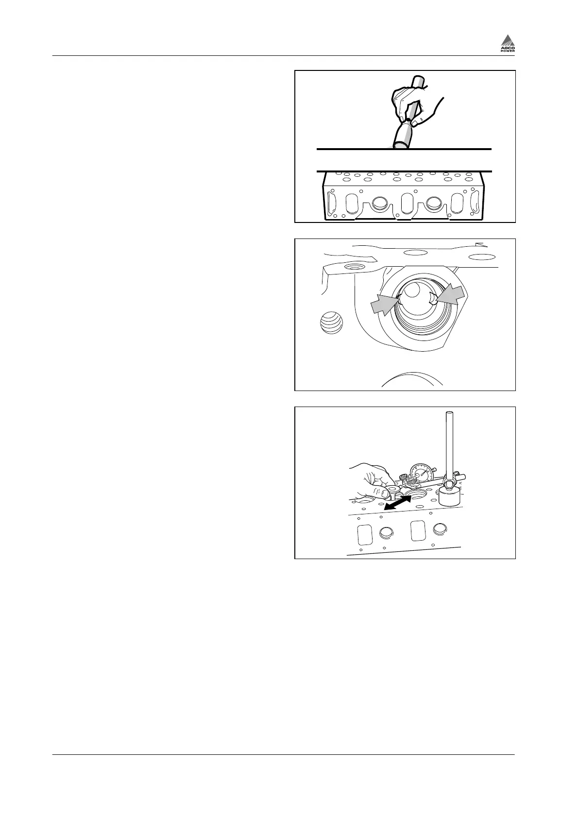
3.
Check the flatness of the cylinder head
against a straight edge.
• An uneven or warped surface need to be
surface ground.
• The height of the cylinder head, after
grinding, can not be less than 109.50 mm.
• The valve disc depth from the cylinder
head surface must be 0.60 mm for the
exhaust valves and 0.80 mm for the inlet
valves.
Fig. 18
4.
Straighten and clean the injector location
seat in the cylinder head with cutter 9120
85400.
5.
Check that the location for the side feed pipe
is clean, especially the grooves for the guide
balls.
Fig. 19
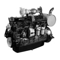
6.
Measure the clearance between the valve
stem and the valve guide with a dial gauge.
a) Lift the valve so that the valve head is 15
mm from the face of the cylinder head,
and measure the clearance.
The clearance must not be greater than
0.30 mm for the inlet valves and 0.35 mm
for the exhaust valves.
b) Use a new valve when measuring, in
order to find out the valve guide wear.
Fig. 20
3. Maintenance
3-16 4th Generation Engines
8370 79492