Chapter 3 Methods and Mappings78
USG-CUS-059 Rev05MassARRAY® Nanodispenser RS1000 v2.1 User Guide
For Research Use Only. Not for use in diagnostic procedures.
NOTE
The save button appears on the last Mapping screen after you start defining plate-to-SpectroCHIP
Array mappings. If you tap the exit button you are prompted to confirm discarding the changes.
Tap ok to discard the changes and return to the first Mapping screen. Tap cancel to remain on the
current screen.
5. Repeat step 2 to step 4 to define the next aspirate-dispense cycle. Continue to repeat
these steps until all of the necessary aspirate-dispense cycles have been defined.
Figure 3.29 shows an example in which two aspirate-dispense cycles have been
defined.
NOTE
Partial plate and SpectroCHIP Array mappings are valid. All of the plate wells and SpectroCHIP
Array pads do not have to be used.
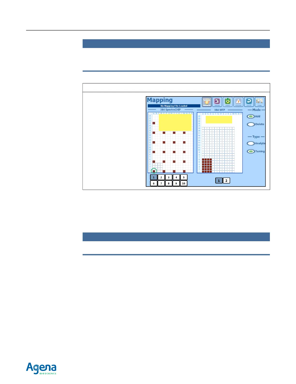
Figure 3.28 Select the SpectroCHIP Array Pad to Receive Pin A1
Pad A1 was selected in this
example. This sets the
location of the lower left
corner of the 6 x 4 pin array
footprint. Pin A1 will dispense
to pad A1.
The 24-pin array footprint is
spread out across every fourth
pad.
SpectroCHIP
Array pads
Plate wells