Chapter 3 Methods and Mappings 83
USG-CUS-059 Rev05MassARRAY® Nanodispenser RS1000 v2.1 User Guide
For Research Use Only. Not for use in diagnostic procedures.
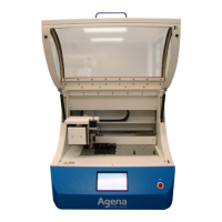
Figure 3.33 Select the Plate Well to Receive Pin A1
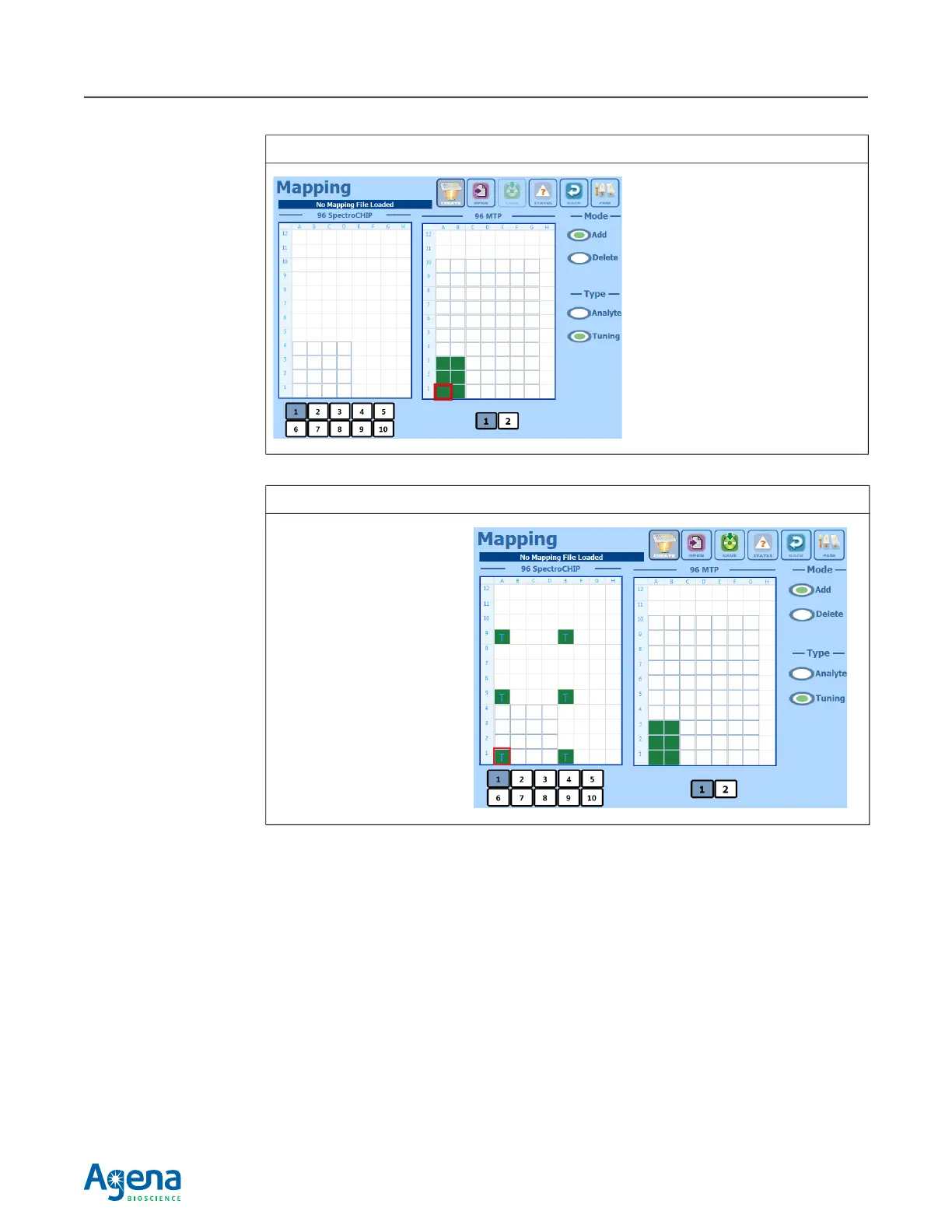
Figure 3.34 Select the SpectroCHIP Array Pad to Receive Pin A1
Well A1 was selected in this
example. The selected well sets
the location of the lower left corner
of the pin array footprint
Pin A1 will aspirate from well A1.
The contiguous wells in a 3 x 2
grid are automatically selected
and the remaining pins will
aspirate from these wells.
Pad A1 was selected in this
example. This sets the
location of the lower left
corner of the 3 x 2 pin array
footprint. Pin A1 will dispense
to pad A1.
The 6-pin array footprint is
spread out across every
eighth pad.
The same color is used in the
plate and SpectroCHIP Array
diagrams to identify the wells
and pads that are mapped to
each other.