7-6 i3070 Series 5i Help
Replacement Procedures
Installation
1 Remove the new card from the ESD-safe bag. Hold it only by the board
handle and board edges to reduce the probability of ESD damage and
contamination.
2 If replacing a Module Control Card, record the 12- digit hardware
address before installing it. The hardware address is printed on a label
on the rear corner of the card.
3 Install the card with its component side facing the same way as the
other cards in the module. Push firmly to seat the card in the
connector, but do not force the card since it can damage the connector.
4 Reconnect cables as needed.
To prevent electrostatic discharge (ESD) from damaging sensitive components on
module/slot cards, wear a tested, grounded, anti-static wrist strap while performing this
procedure. Connectors for the wrist strap are provided at the front of the system
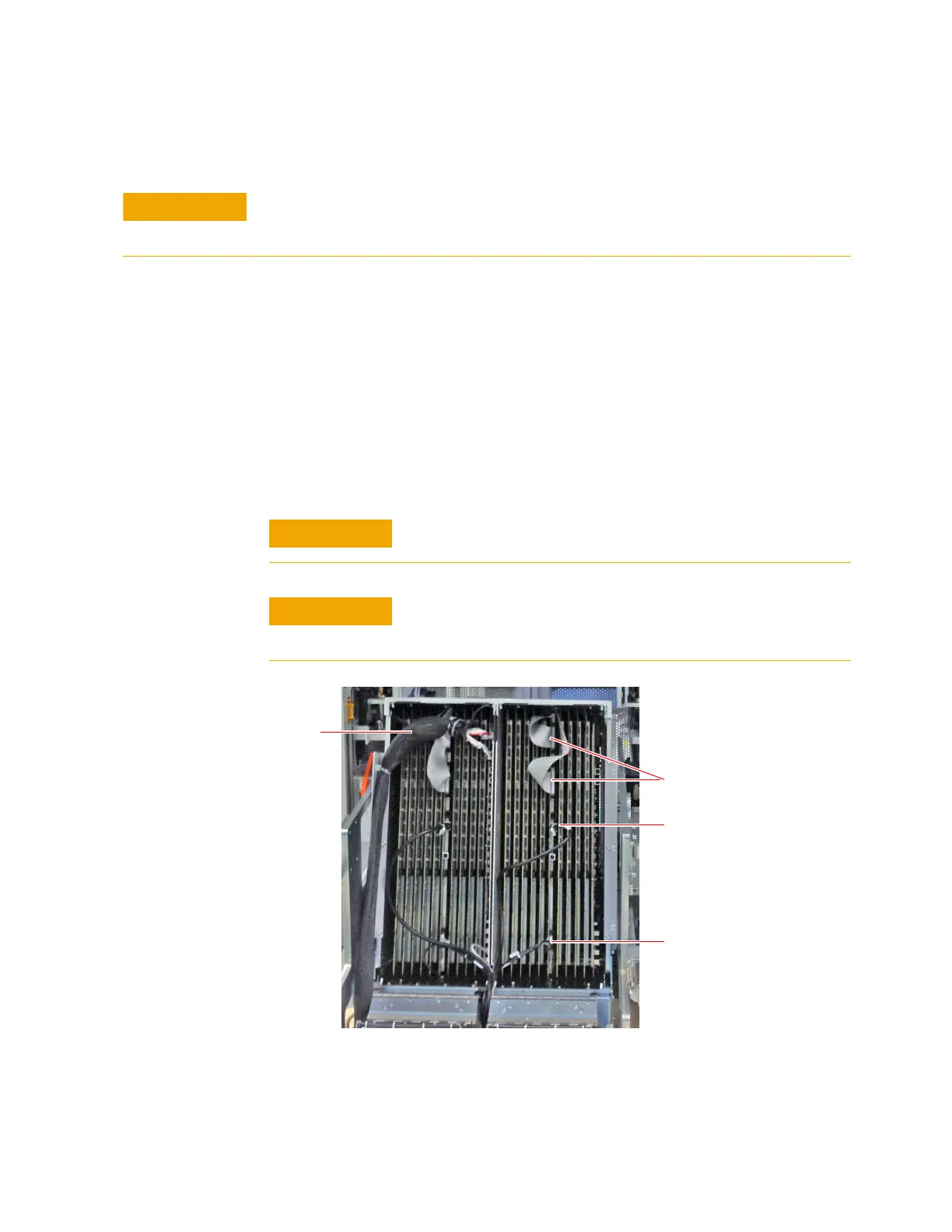
It is very easy to bend connector pins when reconnecting the DUT
power supply cables. Be sure to align the connectors carefully.
Failure to maximize air flow by proper cable routing will cause "hot
spot" overheating. Overheating will shorten the useful life of digital
components on module cards.
High-speed Link Cables
Ethernet Cable
Module Control Cable
DUT cable

 Loading...