Service Guide E8361-90001 4-41
PNA Series Microwave Network Analyzers Troubleshooting
E8361A Measurement System Troubleshooting
Source Group Tests
NOTE A defective A22 switch can exhibit the same symptom as a faulty source.
Therefore, if it is determined that the source is functioning properly, you are
directed to “Checking the Signal Separation Group” on page 4-49.
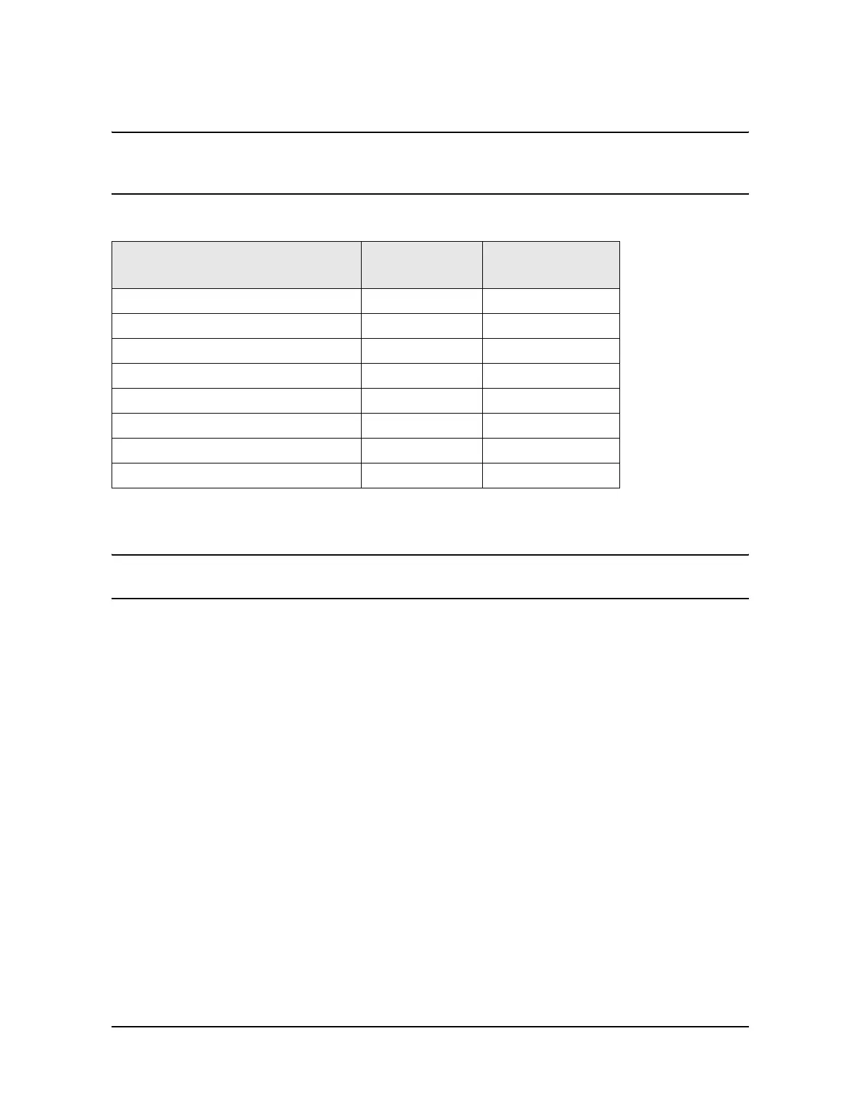
Equipment Used for These Tests
Getting Ready to Test
Before checking the assemblies, you must open the analyzer.
CAUTION Use an antistatic work surface and wrist strap to reduce the chance of
electrostatic discharge for all of the procedures in this chapter.
1. Turn off the analyzer power.
2. Unplug the power to the analyzer and disconnect all rear panel connections.
3. Remove the covers from the analyzer. Refer to “Removing the Covers” on page 7-6.
4. With the covers off, plug in the analyzer and turn on the power.
Single vs. Broadband Failure
There are two main types of failures that are related to the source group. The failures are
classified as:
• broadband
•single band
Single band failures are indicated by all four channel traces having partial dropouts across
the frequency range or intermittent phase lock problems. Troubleshooting information is
provided under “If the traces faults are band-related,” under “All Traces” on page 4-32.
Broadband failures are indicated by all four channel traces being in the noise floor. Most
often this is due to problems in the phase lock signal path and will be characterized by a
“PHASE LOCK LOST” error message on the display.
Equipment Type
Model or
Part Number
Alternate Model
or Part Number
Spectrum analyzer 8565E None
Power meter E4418B/19B E4418A/19A
Power sensor, 1.85 mm V8486A None
RF cable, SMA (f) to SMA (f) Any Any
SMB (m) to SMA (f) adapter 1250-0674 Any
SMA (m) to SMA (m) adapter 1250-1159 Any
Power sensor, 2.4 mm 8487A None
RF cable, 2.4 mm (f) to 2.4 mm (f) 85133C Any
 Loading...


