3-22 Service Guide E8361-90001
Tests and Adjustments PNA Series Microwave Network Analyzers
System Verification E8361A
Performing System Verification
The following verification procedure is automated by the analyzer firmware. For each
verification device, the analyzer reads a file from the verification disk and sequentially
measures the magnitude and phase for all four S-parameters.
NOTE Although the performance for all four S-parameters are measured, the S
11
and S
22
phase uncertainties for the attenuators and airlines are less
important for verifying system performance. Therefore, the limit lines will
not appear on the printout.
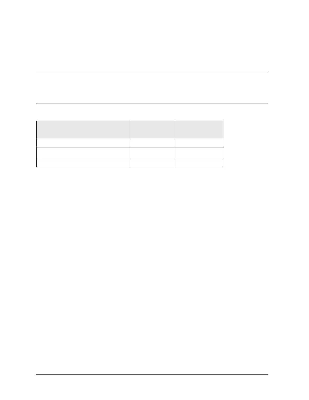
Equipment Used in the System Verification Procedure
Cable Substitution
The test port cables specified for the network analyzer system have been characterized for
connector repeatability, magnitude and phase stability with flexing, return loss, insertion
loss, and aging rate. Since test port cable performance is a significant contributor to the
system performance, cables of lower performance will increase the uncertainty of your
measurement. Refer to the plots in the cable tests (earlier in this chapter) that show the
performance of good cables. It is highly recommended that the test port cables to be
regularly tested.
If the system verification is performed with a non-Agilent cable, ensure that the cable
meets or exceeds the specifications for the test cable specified in the above table,
“Equipment Used in the System Verification Procedure.” Refer to the cable’s user’s guide
for specifications.
Kit Substitution
Non-Agilent calibration kits and verification kits are not recommended nor supported.
Equipment Type
Model or
Part Number
Alternate Model
or Part Number
Calibration kit, 1.85 mm 85058B 85058E
Verification kit, 1.85 mm
E8058V
a
a. Available in May of 2003.
None
Test cable, 1.85 mm (f) to 1.85 mm (f) N4697E N4697-60200
 Loading...


