5-16 Service Guide E8361-90001
Theory of Operation PNA Series Microwave Network Analyzers
Signal Separation Group Operation E8361A
Signal Separation Group Operation
The signal separation group divides the source signal into a reference path and a test path.
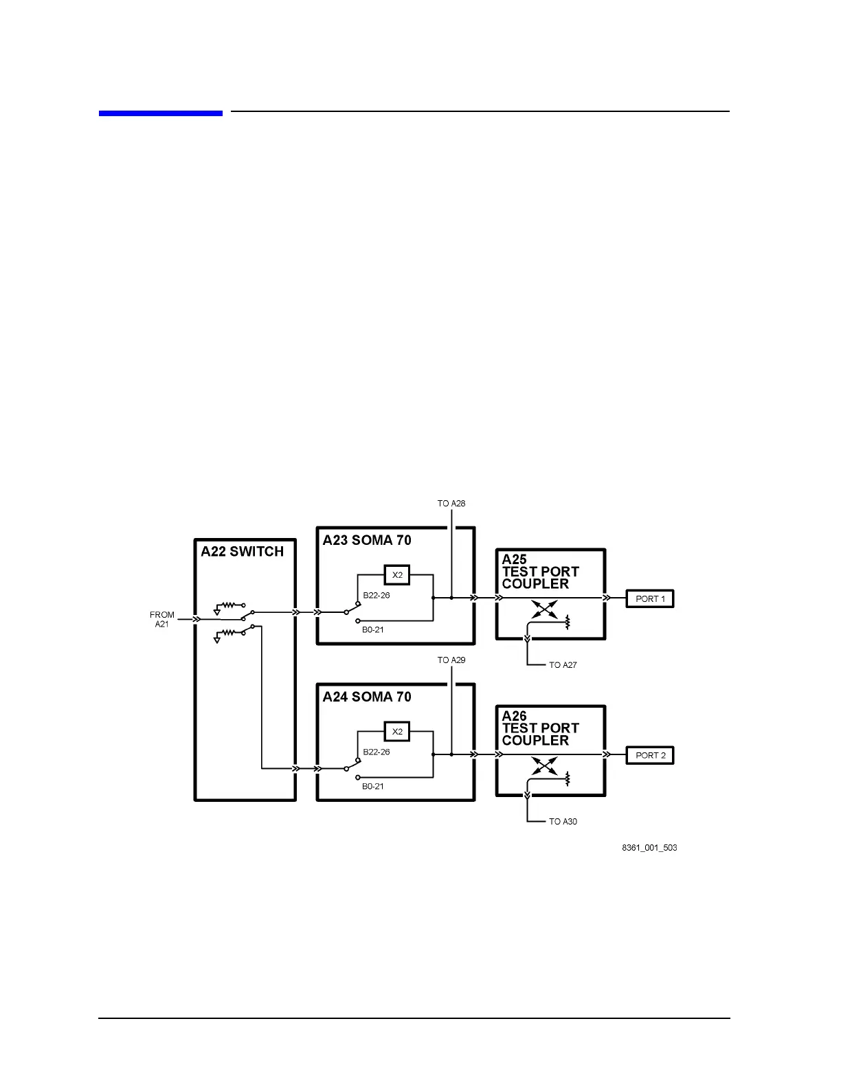
Refer to Figure 5-3 on page 5-16.
• The reference signal is transmitted to the receiver group.
• The test signal is transmitted through—and reflected from—the device under test
(DUT) and then is transmitted to the receiver group.
• Control lines to this group are routed from the A16 test set motherboard.
In this section, the following assemblies are described:
• A22 Switch
• A23 and A24 Source Multiplier/Amplifier 70 (SOMA 70)
• A25 and A26 Test Port Couplers
• Front Panel Jumpers (Option 014 Configurable Test Set)
Figure 5-3 Signal Separation Group, Standard Analyzer
 Loading...


