Service Guide E8361-90001 4-49
PNA Series Microwave Network Analyzers Troubleshooting
E8361A Measurement System Troubleshooting
Checking the Signal Separation Group
Before checking the signal separation group, perform the following procedures:
• “Getting Ready to Test” on page 4-41
Checking the Output Power of the A and B Signals
Using a power meter, you can measure the outputs of the A and B signals from the front
panel. The measurement results will help you isolate a faulty assembly. The outputs of the
R1 and R2 channels cannot be measured because it would necessitate breaking the phase
lock loop, causing all of the signals to be lost.
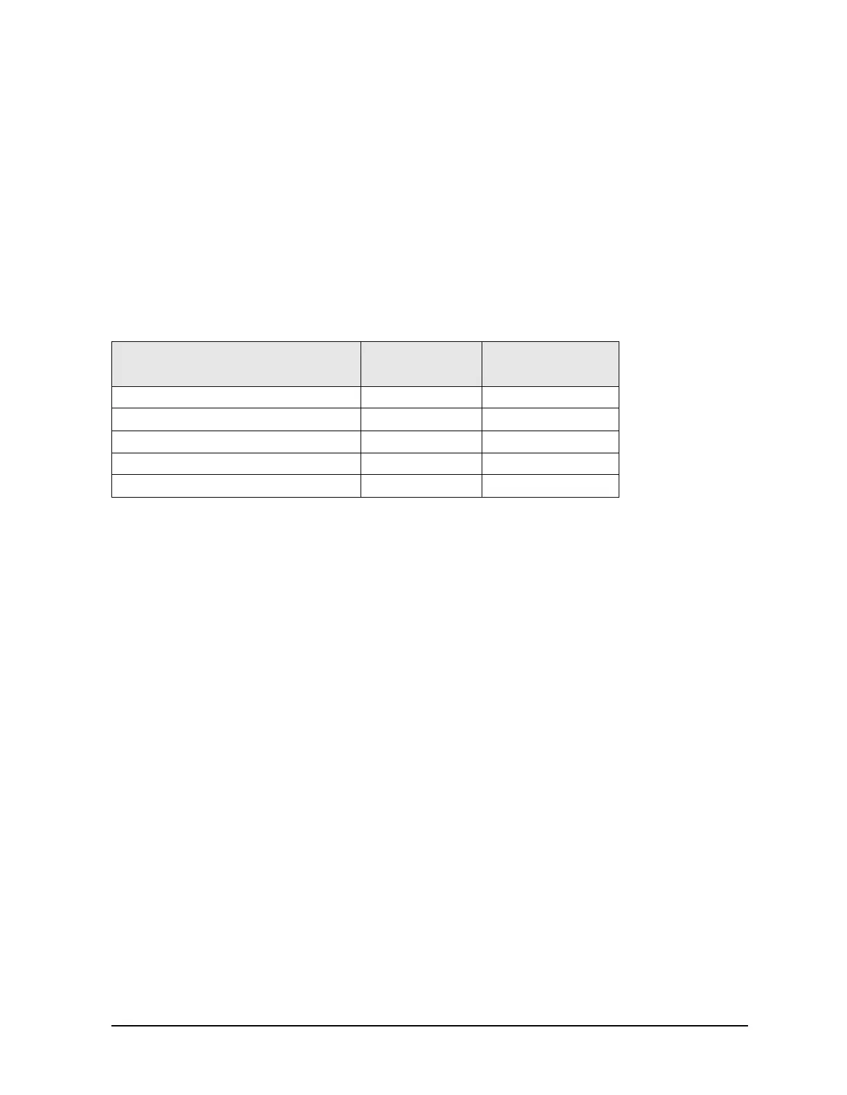
Equipment Used for These Tests
Equipment Setup
1. Before starting these checks, zero and calibrate the power meter. (See the power meter
user’s guide for instructions on setting the calibration factor.)
2. If the
Receiver Display (Figure 4-9) is not on the analyzer screen, perform the following:
On the
System menu, point to Service, Utilities, and then click Receiver Display.
3. Set the sweep speed for a 10 second sweep: On the Sweep menu, click Sweep Time and
set the time to 10.000 seconds in the
Sweep Time box.
Checking Port 1 Power (A Signal)
The object of this check is to verify the power of the A signal across the entire frequency
range. Perform this test if there is an observed problem only with the channel A trace. The
ten second sweep is slow enough to allow you to observe the output power on the power
meter as the sweep occurs.
1. Connect the power sensor to Port 1.
2. Observe the power reading on the power meter as the sweep occurs on the analyzer.
3. The measured output power on the power meter should be within −15 dBm ±4 dB for all
E8361A PNAs, over the entire frequency range.
• If the measured power is correct, go to “Checking the Receiver Group” on page 4-52.
• If the measured power is not correct, go to “Checking the Signal through the Signal
Separation Path” on page 4-50.
Equipment Type
Model or
Part Number
Alternate Model
or Part Number
Power meter E4418B/E441B E4418A/E4419A
Power sensor, 1.85 mm V8486A None
Adapter, 3.5 mm (f) to 3.5 mm (f) 83059B 85052-60012
Power sensor, 2.4 mm 8487A None
Adapter, 2.4 mm (f) to 2.4 mm (f) 11900B 85056-60007
 Loading...


