4-50 Service Guide E8361-90001
Troubleshooting PNA Series Microwave Network Analyzers
Measurement System Troubleshooting E8361A
Checking Port 2 Power (B Signal)
The object of this check is to verify the power of the B signal across the entire frequency
range. Perform this test if there is an observed problem only with the channel B trace. The
ten second sweep is slow enough to allow you to observe the output power on the power
meter as the sweep occurs.
1. Connect the power sensor to Port 2.
2. Observe the power reading on the power meter as the sweep occurs on the analyzer.
3. The measured output power on the power meter should be within −15 dBm ±4 dB for all
E8361A PNAs, over the entire frequency range.
Checking the Signal through the Signal Separation Path
For all of the following checks, refer to the block diagrams at the end of this chapter and to:
• “Bottom Assemblies, No Options” on page 6-21
1. “Bottom RF Cables, No Options” on page 6-23
Port 1 trace loss in the signal separation group is due to one or more of the following
assemblies being defective:
•A22 switch
• A25 test port 1 coupler
Port 2 trace loss in the signal separation group is due to one or more of the following
assemblies being defective:
•A22 switch
• A26 test port 2 coupler
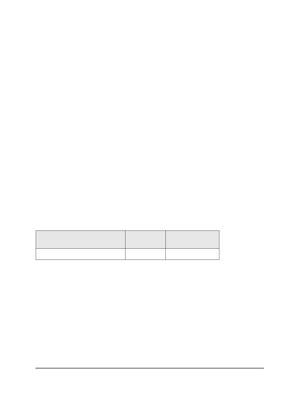
Equipment Used for These Tests
To determine which assembly is defective, check the signal at each available measurement
point in the signal path from the A22 switch to the test port coupler.
For Port 1 measurements, set the network analyzer for an S
11
measurement with a CW
frequency of 1 GHz.
For Port 2 measurements, set the network analyzer for an S
22
measurement with a CW
frequency of 1 GHz.
Perform the following checks in the order presented.
Equipment Type
Model or
Part Number
Alternate Model
or Part Number
Spectrum analyzer 8565E
856xE
1
1. Must be capable of measuring a signal at 1 GHz.
 Loading...


