Service Guide E8361-90001 4-51
PNA Series Microwave Network Analyzers Troubleshooting
E8361A Measurement System Troubleshooting
Checking the A22 Switch
1. Locate the following semirigid cable at the A22 switch:
All . . . . . . . . . . . . . . . . . . . . . . . . . . . . . .W3 for Port 1 or W4 for Port 2
2. Using a 5/16-inch torque wrench, disconnect the semirigid cable at the A22 switch.
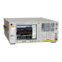
3. Connect the spectrum analyzer to the connector. Set the spectrum analyzer to measure
a signal at 1 GHz.
4. If the 1 GHz signal is not present, replace the A22 switch. Refer to “Removing and
Replacing the A22 Switch” on page 7-42.
5. If the 1 GHz signal is present, replace the cable and then continue with “Checking the
A23 and A24 SOMA 70s and the A25 and A26 Test Port Couplers” on page 4-51.
Checking the A23 and A24 SOMA 70s and the A25 and A26 Test Port Couplers
1. Locate the following semirigid cable at the SOMA 70:
A23 SOMA 70 (no options). . . . . . . . . . .W5 for Port 1
A23 SOMA 70 (option 014). . . . . . . . . . .W61 for Port 1
A24 SOMA 70 (no options). . . . . . . . . . .W6 for Port 2
A24 SOMA 70 (option 014). . . . . . . . . . .W62 for Port 1
2. Using a 5/16-inch torque wrench, disconnect the semirigid cable at the SOMA 70 (as
required).
3. Connect the spectrum analyzer to the connector. Set the spectrum analyzer to measure
a signal at 1 GHz.
4. If the 1 GHz signal is not present, replace the SOMA 70 (as required). Refer to
“Removing and Replacing the A23 and A24 SOMA 70s” on page 7-44.
5. If the 1 GHz signal is present, replace the test port coupler (as required). Refer to
“Removing and Replacing the A25 and A26 Test Port Couplers” on page 7-46.

 Loading...


