4-54 Service Guide E8361-90001
Troubleshooting PNA Series Microwave Network Analyzers
Measurement System Troubleshooting E8361A
Checking the Frequency Offset Group (Option 080)
CAUTION This section troubleshoots only those circuits specifically related to the
frequency offset group (option 080). Please refer to “Where to Begin
Troubleshooting” on page 4-31 and refer to the appropriate standard
S-parameter test—with frequency offset mode off—before proceeding with
this section.
Frequency Offset Group Tests
NOTE A defective A22 switch can exhibit the same symptom as a faulty source.
Therefore, if it is determined that the source is functioning properly, you are
directed to “Checking the Signal Separation Group” on page 4-49.
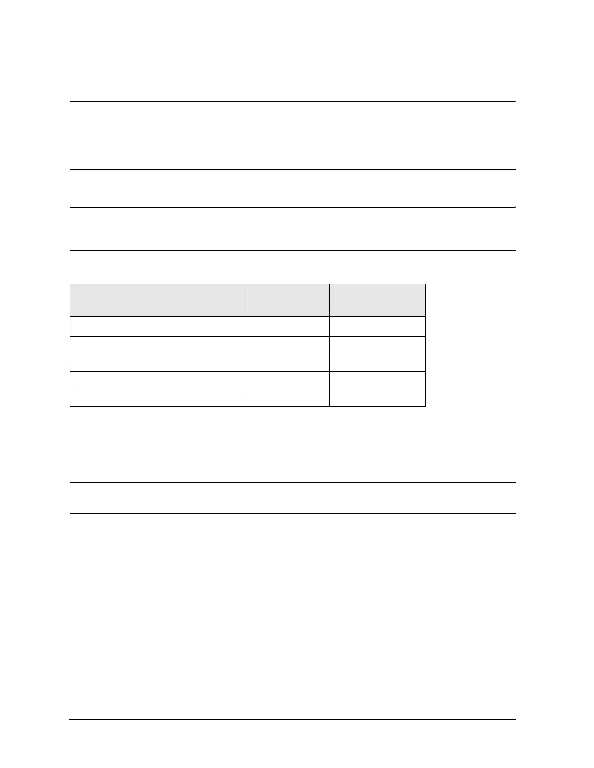
Equipment Used for These Tests
Getting Ready to Test
Before checking the assemblies, you must open the analyzer.
CAUTION Use an antistatic work surface and wrist strap to reduce the chance of
electrostatic discharge for all of the procedures in this chapter.
1. Turn off the analyzer power.
2. Unplug the power to the analyzer and disconnect all rear panel connections.
3. Remove the covers from the analyzer. Refer to “Removing the Covers” on page 7-6.
4. With the covers off, plug in the analyzer and turn on the power.
5. From
Channel, click Frequency Offset. In the Frequency Offset dialog box, click in the
Frequency Offset on/off box to select. Click OK.
Checking the A10 5 MHz Reference Output
1. Refer to the block diagram at the end of this chapter and to “Top Cables, All Options
Including 080” on page 6-19. Locate flexible cable W94, at the A10 frequency reference
board, A10J11.
Equipment Type
Model or
Part Number
Alternate Model
or Part Number
Spectrum analyzer 8565E
856xE
1
1. Must be capable of measuring signals at 1 MHz, 8.333 MHz and
41.667 MHz.
RF cable, 3.5 mm (f) to 3.5 mm (f) 85131C Any
RF cable, 2.4 mm (f) to 2.4 mm (f) 85133C Any
Adapter, 3.5 mm (f) to 3.5 mm (f) 83059B 85052-60012
Adapter, 2.4 mm (f) to 2.4 mm (f) 11900B 85056-60007
 Loading...


