Service Guide E8361-90001 5-3
PNA Series Microwave Network Analyzers Theory of Operation
E8361A Network Analyzer System Operation
Network Analyzer System Operation
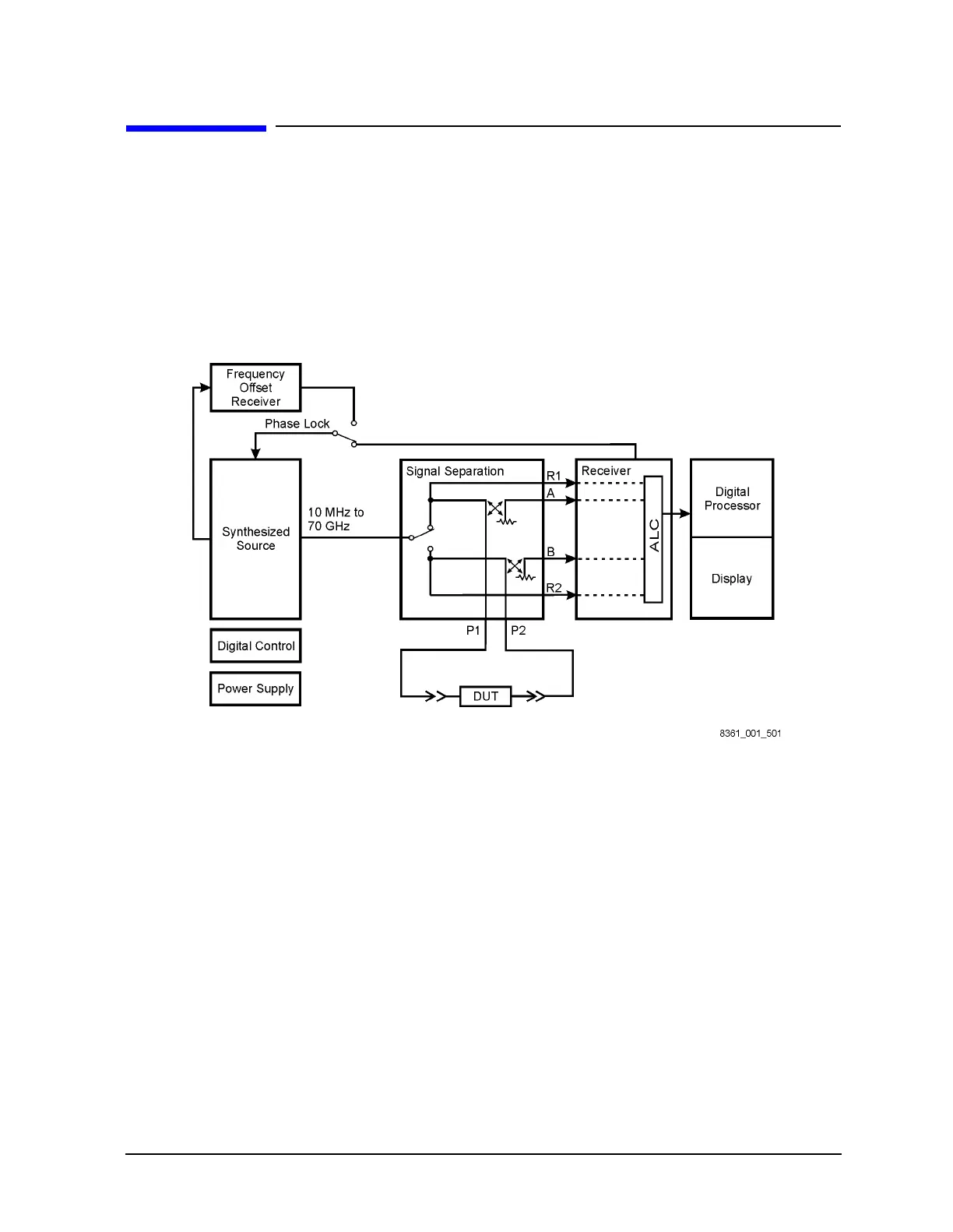
The PNA series network analyzer generates a phase-locked incident signal from the
internal synthesized source. By means of signal separation, the incident signal is divided
into a reference signal and a test signal. The reference signal is applied to the receiver
group, while the test signal is applied to the device under test (DUT) and then to the
receiver group. The signals are downconverted and are next sampled and digitally
processed. Figure 5-1 is a simplified block diagram of the network analyzer system.
Figure 5-1 System Simplified Block Diagram
Functional Groups of the Network Analyzer
The operation of the network analyzer can be separated into six functional groups. Each
group consists of several major assemblies that perform a distinct function in the
instrument. Some of the assemblies are related to more than one group, and all the groups,
to some extent, are interrelated and affect each other’s performance. The six major
functional groups are:
• Synthesized Source Group
• Signal Separation Group
• Receiver Group
• Frequency Offset Group
• Digital Processor and Digital Control Group
• Power Supply Group
 Loading...


