Rockwell Automation Publication 1766-UM001I-EN-P - June 2015 87
Using the LCD Chapter 5
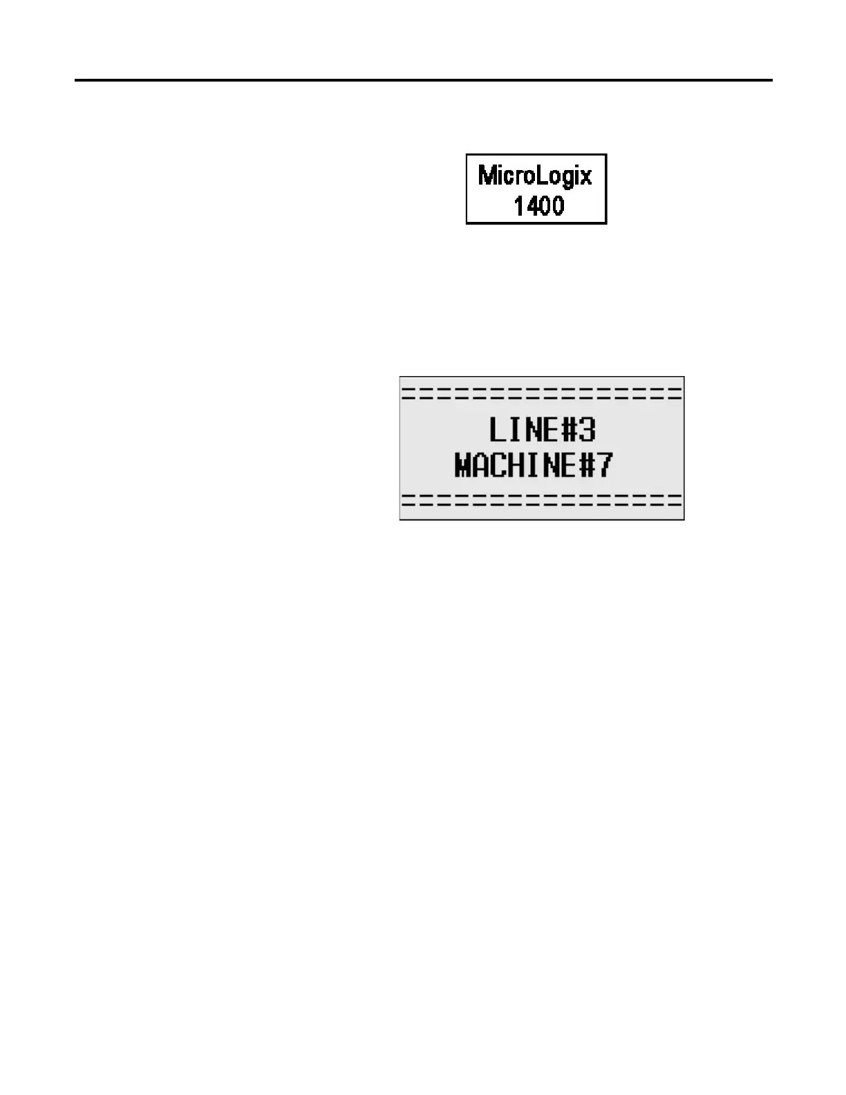
LCD Default Startup Screen
You can customize this Startup screen in your application program by defining a
ASCII data file that contains the bitmap format image to display on the Startup
screen and specifying the CBL element of the LCD Function File to the address
of this ASCII file.
The screen shown below is an example of a customized Startup screen.
Your imported Bitmap file format should meet the following criteria:
• image resolution : 128 x 64 pixels (black/white image)
• image size : 1088 bytes
(consisting of image header = 62 bytes
+ raw image data size = 1024 bytes
+ padding data : 2 bytes)
To load a customized boot logo image to your controller, the CBL (Customized
Boot Logo ASCII File) element in the LCD Function File should be configured
properly. If the CBL element is set to 0 (default) or if the indexed ASCII file does
not exist, the embedded default logo will be displayed.

 Loading...


