EasyManuals Logo

Allen-Bradley MicroLogix 1400 User Manual

Allen-Bradley MicroLogix 1400
404 pages
To Next Page IconTo Next Page
To Previous Page IconTo Previous Page
Page #116 background imageLoading...
Page #116 background image
102 Rockwell Automation Publication 1766-UM001I-EN-P - June 2015
Chapter 5 Using the LCD
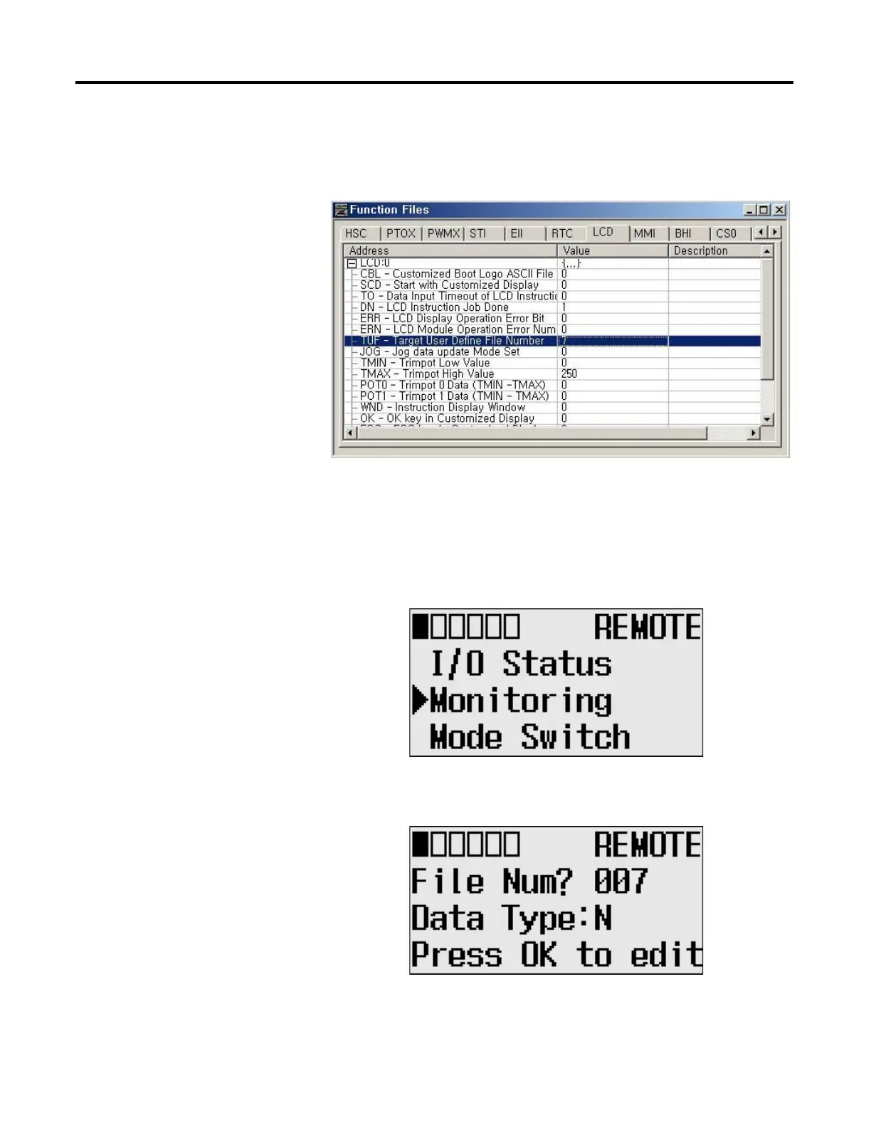
• The TUF element of the LCD Function File is set to 7 to specify the
integer file N7 as the target integer file to monitor on the LCD, as shown
in the screen capture below.
• The controller mode is set to REMOTE RUN.
Follow these steps to view and change the data values of the integer file N7.
1. On the Main Menu screen, select Monitoring by using the Up and Down
keys on the LCD keypad.
2. Press the OK key on the LCD keypad. The File Number prompt is
displayed.
3. If Integer is selected, as shown in step 2, press the OK key.
If not selected, press the Down key to select it and then press the OK key.

Table of Contents

Other manuals for Allen-Bradley MicroLogix 1400

Questions and Answers:

Question and Answer IconNeed help?

Do you have a question about the Allen-Bradley MicroLogix 1400 and is the answer not in the manual?

Allen-Bradley MicroLogix 1400 Specifications

General IconGeneral
Processor32-bit
Expansion ModulesUp to 7 expansion I/O modules
Power Supply24V DC or 120/240V AC
Programming SoftwareRSLogix 500
Communication PortsEthernet, RS-232/RS-485 combo port
Controller TypeProgrammable Logic Controller (PLC)
SeriesMicroLogix
Digital Outputs12
Analog Inputs6 (embedded)
Analog Outputs2 (embedded)
High-Speed Counter6 high-speed counters
Pulse Output2 (embedded)
Ethernet PortYes

Related product manuals