EasyManuals Logo

Allen-Bradley MicroLogix 1400 User Manual

Allen-Bradley MicroLogix 1400
404 pages
To Next Page IconTo Next Page
To Previous Page IconTo Previous Page
Page #117 background imageLoading...
Page #117 background image
Rockwell Automation Publication 1766-UM001I-EN-P - June 2015 103
Using the LCD Chapter 5
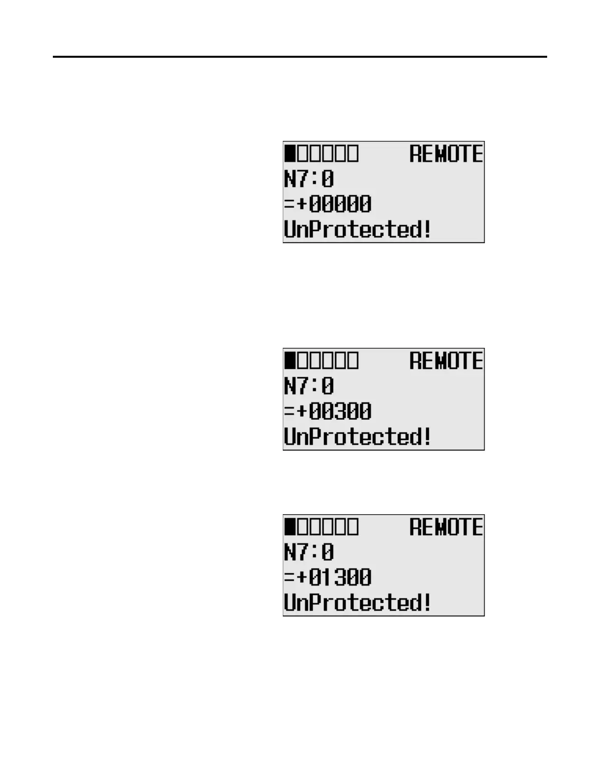
4. The current data value (ON) of the N7:0 word is displayed. Note that the
target word “0”, which is right next to “N7:”, is flashing, which means the
cursor is at the target word position.
5. We will change the data value of the N7:0 word to the negative decimal
value -1300. First, press OK to move the cursor to the data value position.
Then, the last digit of “+00000” will be flashing, which means the cursor is
at the data value position.
6. Press the Left key twice. Then, the cursor will position at the third digit.
Press the Up key three times to change the third digit to 3.
7. Press the Left key once. Then, press the Up key once. The second digit will
change to “1”. Note that “1” is still flashing, which means the cursor is still
at the data value position.

Table of Contents

Other manuals for Allen-Bradley MicroLogix 1400

Questions and Answers:

Question and Answer IconNeed help?

Do you have a question about the Allen-Bradley MicroLogix 1400 and is the answer not in the manual?

Allen-Bradley MicroLogix 1400 Specifications

General IconGeneral
Processor32-bit
Expansion ModulesUp to 7 expansion I/O modules
Power Supply24V DC or 120/240V AC
Programming SoftwareRSLogix 500
Communication PortsEthernet, RS-232/RS-485 combo port
Controller TypeProgrammable Logic Controller (PLC)
SeriesMicroLogix
Digital Outputs12
Analog Inputs6 (embedded)
Analog Outputs2 (embedded)
High-Speed Counter6 high-speed counters
Pulse Output2 (embedded)
Ethernet PortYes

Related product manuals